
Tracker 4WD L4-1.6L VIN 6 (1998)
Throttle Position Sensor: Adjustments
Tool Required
^
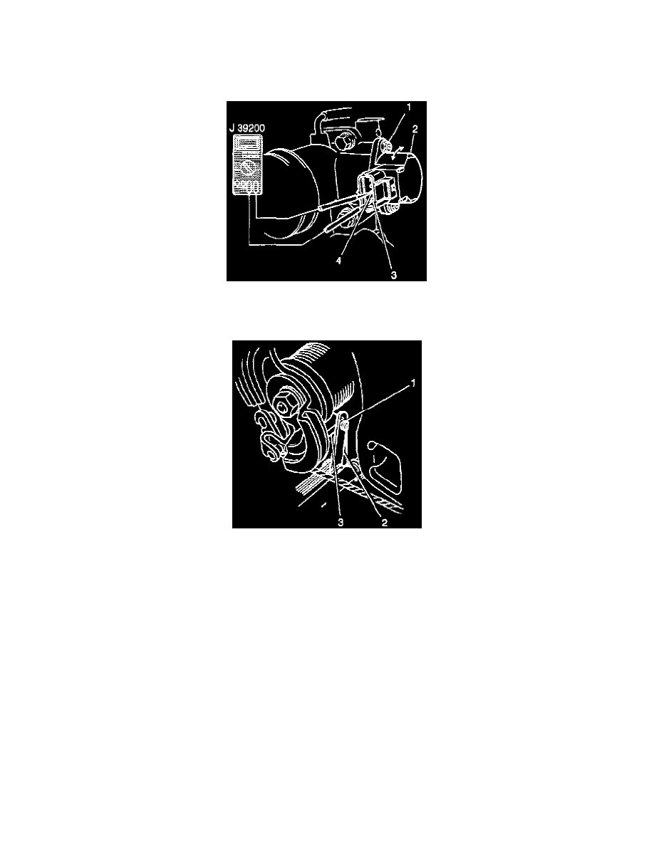
J-39200, Digital multimeter.
NOTE: The throttle valve must be in the closed position for correct measurements.
Procedure
1. Connect a DMM to the TP sensor terminal 1 (3) to 2 (4).
2. Measure the resistance.
3. Insert a 0.65 mm (0.026 in) feeler gauge (2) between the throttle stop screw (1) and the throttle lever (3).
4. With the retaining screws (1) loosely installed, turn the TP sensor (2) fully counterclockwise.
5. Gradually turn the TP sensor clockwise in order to find the position where the ohmmeter reading changes from continuity to no continuity. Tighten
the TP sensor bolts to 2.5-4.5 Nm (22.8-38.4 lb in).
6. Remove the feeler gauge. The DMM should still indicate continuity.
7. Insert the 0.8 mm (0.037 in) feeler gauge between the throttle stop screw and the throttle lever. The DMM should now indicate an open circuit (no
continuity).
8. Insert the 0.5 mm (0.020 in) feeler gauge between the throttle stop screw and the throttle lever. The DMM should indicate continuity. If steps 6, 7
or 8 are unsatisfactory, return to step 1 and repeat the entire procedure.