
Tracker 4WD L4-1.6L VIN 6 (1998)
Throttle Position Sensor: Testing and Inspection
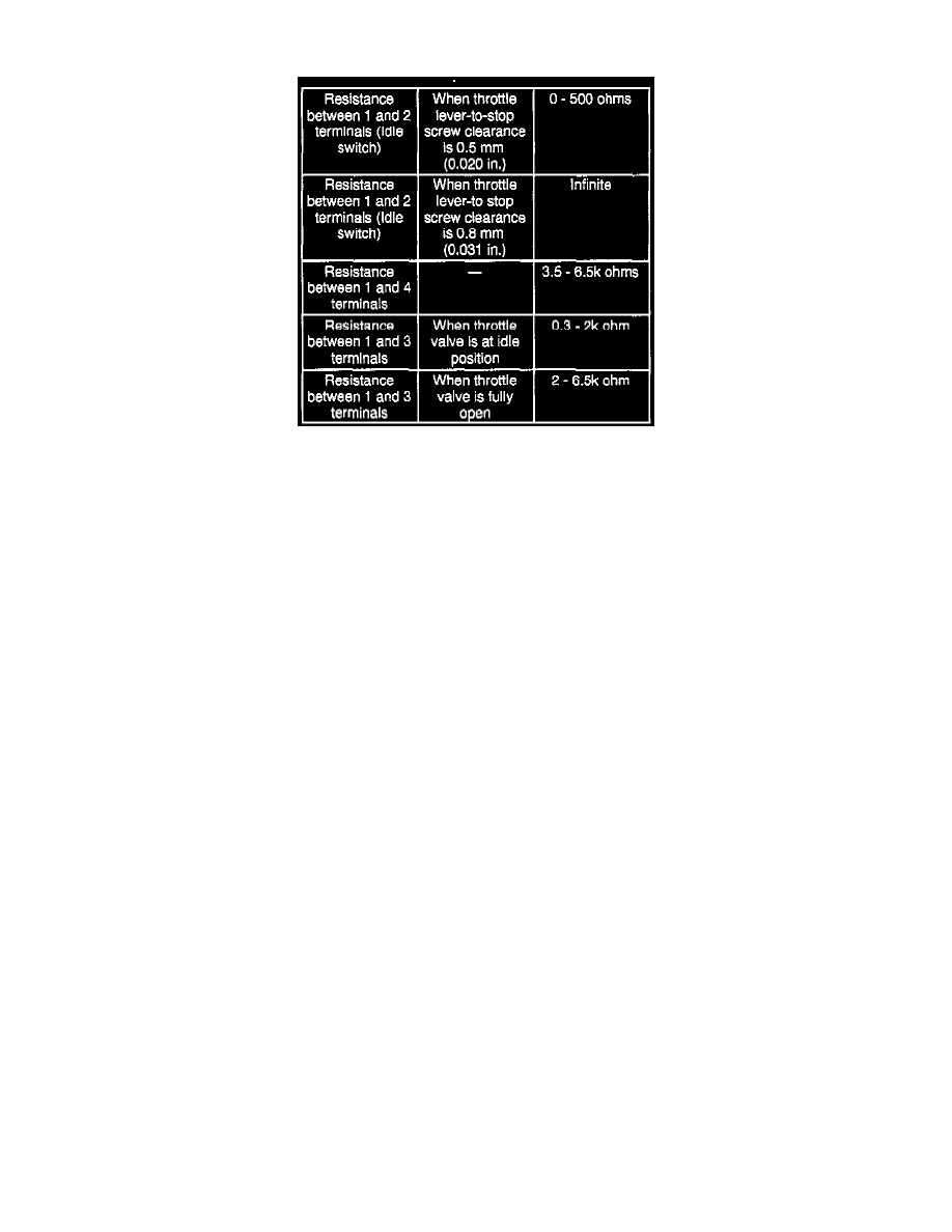
TP Sensor Output Check Table
Tool Required
^
J-39200, Digital multimeter.
Procedure
1. Disconnect the negative battery cable.
2. Disconnect the Throttle Position (TP) sensor electrical connector.
NOTE: There should be more than 2 k ohms difference between when the throttle valve is at the idle position and when it is fully open.
3. Measure the TP sensor resistance according to the TP Sensor Output Check Table.
4. If the TP sensor resistance is not within the specified ranges, adjust or replace the TP sensor.
5. If the TP Sensor resistance is within the specified ranges, connect the TP electrical connector.
6. Connect the negative battery cable.