
Tracker 4WD L4-1.6L VIN 6 (1998)
in the ring gear, this will produce a contact pattern on the drive side of the ring gear (pinion gear driving ring gear).
4. Turn the pinion gear in the opposite direction with a drag simulated on the ring gear to produce a contact pattern on the coast side of the ring gear
(ring gear driving pinion gear).
INSPECTION PROCEDURE
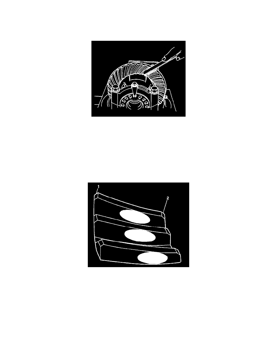
1. Inspect the drive side (2) of the ring gear teeth (concave) and the coast side (1) of the ring gear teeth (convex).
2. Inspect the contact pattern around the ring gear (3). Uneven contact around the ring gear indicates excessive ring gear runout.
3. Inspect the drive pattern. The drive pattern should be centrally located between the top and the bottom of the ring gear teeth. Under an increased
load, the pattern spreads out and tends to move toward the heel of the tooth.
Inspect the toe. To compensate for an increased load the contact pattern can be somewhat closer to the toe.
4. Inspect the heel. Under heavy loading conditions, up hill or rapid acceleration, the pattern may extend almost the full distance between the heel
and the toe.
5. Inspect the pinion gear for the proper selective shim if excessive contact pattern error is present with the proper backlash specification.
HEEL TO TOE PATTERNS
^
A typical drive pattern from heel (2) to toe (1) has a normal drive contact.