
Tracker 4WD L4-1.6L VIN 6 (1998)
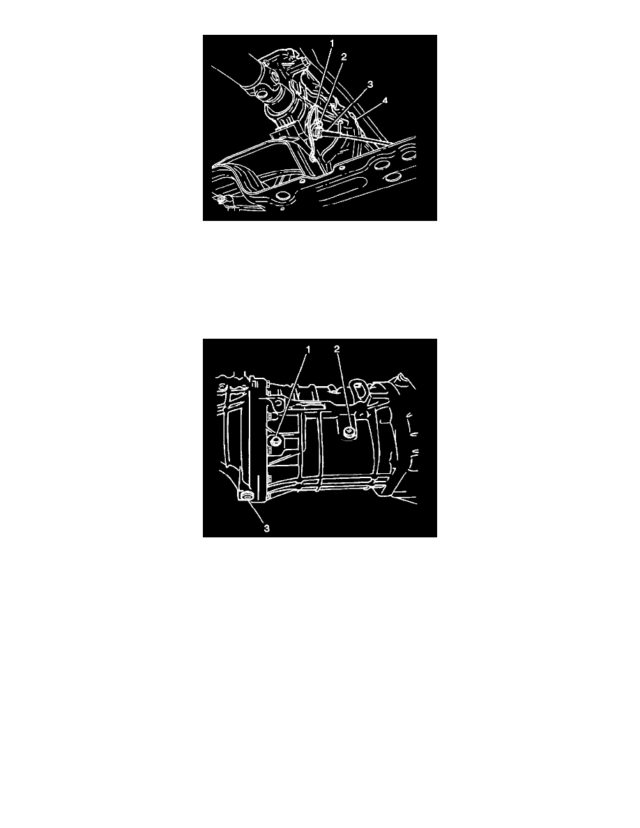
14. Install the speedometer driven gear case and the ground wire (1) to the extension case (4); secure with one bolt (2).
^
Tighten the speedometer driven gear case retaining bolt to 12 Nm (106 inch lbs.).
15. Install the speedometer cable (3) to the speedometer driven gear case.
16. Install the rear propeller shaft into the vehicle aligning the index marks made during the removal procedure; secure with four bolts and four nuts.
^
Tighten the rear propeller shaft bolts and the nuts to 50 Nm (37 ft. lbs.).
17. Apply the GM P/N 12346005, or equivalent, to the threaded portion of the transmission drain plug.
18. Install the transmission drain plug (3) into the transmission.
^
Tighten the transmission drain plug to28 Nm (20 ft. lbs.).
19. Add approximately 1.5 liters (1.6 quarts) of synthetic 75W-90 GL4 lubricant, or equivalent into the transmission oil level/filler plug (2). Oil level
should be even with the bottom of the transmission oil level/filler plug (2) hole.
20. Apply GM P/N 12346004, or equivalent, to the threaded portion of the transmission oil level/filler plug (2).
21. Install the transmission oil level/filler plug (2) into the transmission.
^
Tighten the transmission oil level/filler plug (2) to 28 Nm (20 ft. lbs.).
22. Lower the vehicle.
23. Install four bolts to the fan shroud at the radiator.
^
Tighten the fan shroud bolts to 10 Nm (89 inch lbs.).
24. Install the gearshift control lever into the gearshift lever case. Refer to Gearshift Control Lever Installation.
Rear Case Removal
REMOVAL PROCEDURE
^
Tools Required
-
J29369-01 Output Shaft Bearing Remover
-
J23907 Slide Hammer
-
J35664 Bearing Installer