
Tracker 4WD L4-2.0L VIN C (1999)
Use the connector repair assembly packs in order to repair the damaged SIR/SRS wire harness connectors and the terminals. Do not use the connector
repair assembly pack in order to repair the pigtails. These kits include an instruction sheet and the sealed splices. Use the sealed splices in order to splice
the new wires, connectors, and terminals to the harness. The splice crimping tool is color keyed in order to match the splices from the J 38125-B. You
must use the splice crimping tool in order to apply these splices.
The terminals in the SIR/SRS system are made of a special metal. This metal provides the necessary contact integrity for the sensitive, low energy
circuits. These terminals are only available in the connector repair assembly packs. Do not substitute any other terminals for those in the assembly packs.
If the individual terminals are damaged on the Sensing And Diagnostic Module (SDM) harness connector, use 1 of the following 2 components in order
to replace the SDM harness connector:
^
The SDM harness connector pigtail assembly
^
The SDM harness connector replacement kit
If the individual terminals are damaged on any other SIR/SRS connection, use the appropriate connector repair assembly pack in order to replace the
entire connection. Replace the entire SIR/SRS wiring harness, if needed, in order to maintain SIR/SRS circuit integrity.
SIR/SRS Wire Pigtail Repair
IMPORTANT: Do not make wire, connector, or terminal repairs on components with wire pigtails. A wire pigtail is a wire or wires attached directly
to the device (not by a connector). If a wiring pigtail is damaged, you must replace the entire component (with pigtail). The inflatable restraint steering
wheel module coil is an example of a pigtail component.
SIR/SRS Wire Repair
TOOLS REQUIRED
J 38125-B Terminal Repair kit
IMPORTANT: Determine the correct wire size for the circuit you are repairing. You must obtain this information in order to ensure circuit integrity.
If any wire except the pigtail is damaged, repair the wire by splicing in a new section of wire of the same gauge size (0.5 mm, 0.8 mm, 1.0 mm etc.). Use
the sealed splices and splice crimping tool from the J 38125-B. Use the following wiring repair procedures in order to ensure the integrity of the sealed
splice.
IMPORTANT: You must perform the following procedures in the listed order. Repeat the procedure if any wire strands are damaged. You must obtain
a clean strip with all of the wire strands intact.
1. Open the harness by removing any tape:
^
Use a sewing seam ripper (available from sewing supply stores) in order to cut open the harness in order to avoid wire insulation damage.
^
Use the crimp and sealed splice sleeves on all types of insulation except tefzel and coaxial.
^
Do not use the crimp and sealed splice sleeve to form a splice with more than 2 wires coming together.
2. Cut as little wire off the harness as possible. You may need the extra length of wire in order to change the location of a splice.
Adjust splice locations so that each splice is at least 40 mm (1.5 in) away from the other splices, harness branches, or connectors.
3. Strip the insulation:
^
When adding a length of wire to the existing harness, use the same size wire as the original wire.
^
Perform one of the following items in order to find the correct wire size:
-
Find the wire on the schematic and convert the metric size to the equivalent AWG size.
-
Use an AWG wire gauge.
-
If you are unsure of the wire size, begin with the largest opening in the wire stripper and work down until achieving a clean strip of the
insulation.
^
Strip approximately 7.5 mm (0.313 in) of insulation from each wire to be spliced.
^
Do not nick or cut any of the strands. Inspect the stripped wire for nicks or cut strands.
^
If the wire is damaged, repeat this procedure after removing the damaged section.
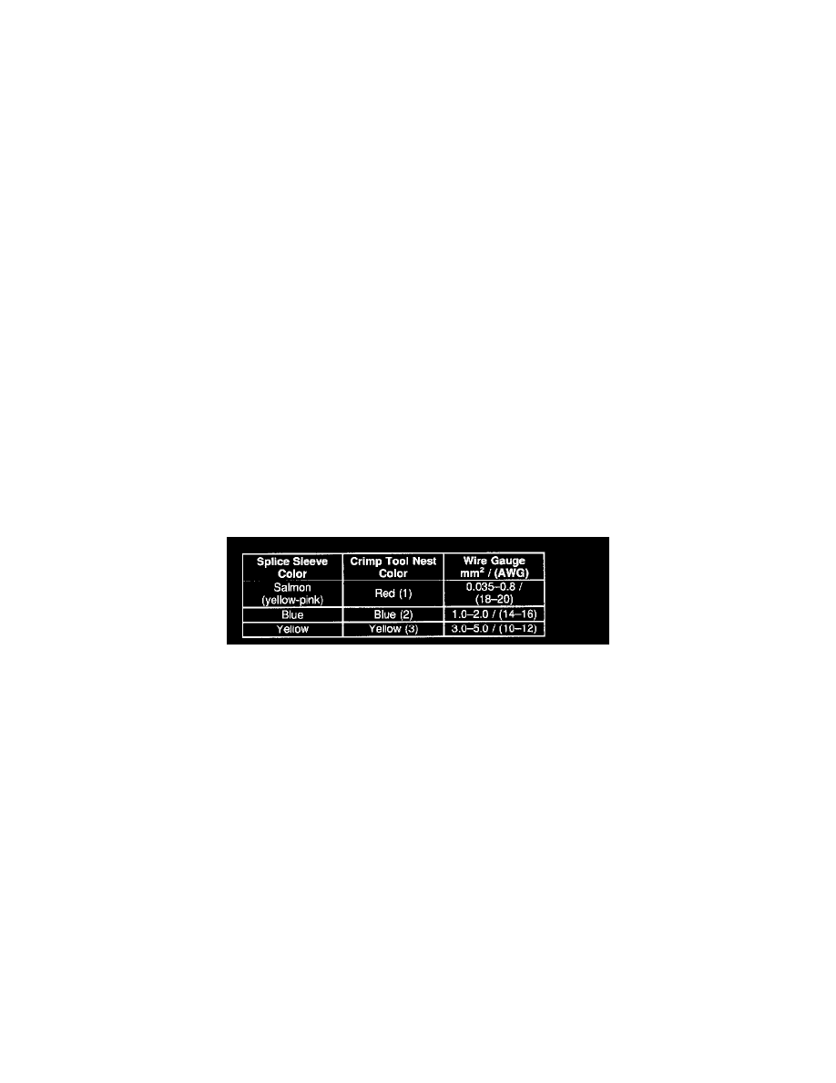
4. Select the proper sealed splice sleeve according to the wire size. Refer to the above table at the beginning of the repair procedure for the color
coding of the splice sleeves and the crimp tool nests.