
Tracker 4WD L4-2.0L VIN C (1999)
Body Control Module: Diagnostic Aids
Basic Knowledge Required
Without a basic knowledge of electricity, it will be difficult to use the diagnostic procedures contained in this section. You should understand the basic
theory of electricity and know the meaning of voltage (volts), current (amps) and resistance (ohms). You should understand what happens in a circuit
with an open or a shorted wire. You should be able to read and understand a wiring diagram.
Checking Aftermarket Accessories
Do not connect aftermarket accessories into the following circuits:
CAUTION: Refer to SIR Service Precautions Caution in Cautions and Notices.
^
SIR circuits, all such circuits are indicated on circuit diagrams with the SIR symbol.
NOTE: Refer to OBD II Symbol Description Notice in Cautions and Notices.
^
OBDII circuits, all such circuits are indicated on circuit diagrams with the OBDII symbol.
Always check for aftermarket accessories (non-OEM) as the first step in diagnosing electrical problems. If the vehicle is so equipped, disconnect the
system to verify that these add-on accessories are not the cause of the problems.
Possible causes of vehicle problems related to aftermarket accessories include:
^
Power feeds connected to points other than the battery.
^
Antenna location.
^
Transceiver wiring located too close to vehicle electronic modules or wiring.
^
Poor shielding or poor connectors on antenna feed line.
^
Check for recent service bulletins detailing installation guidelines for aftermarket accessories.
Connector Position Assurance Locks
The Connector Position Assurance (CPA) is a small plastic insert that fits through the locking tabs of all the SIR system electrical connectors. The CPA
ensures that the connector halves cannot vibrate apart. You must have the CPA in place in order to ensure good contact between the SIR mating
terminals.
Terminal Position Assurance Locks
The Terminal Position Assurance (TPA) insert resembles the plastic combs used in the control module connectors. The TPA keeps the terminal securely
seated in the connector body. Do not remove the TPA from the connector body unless you remove a terminal for replacement.
Push to Seat Connectors
TERMINAL REMOVAL
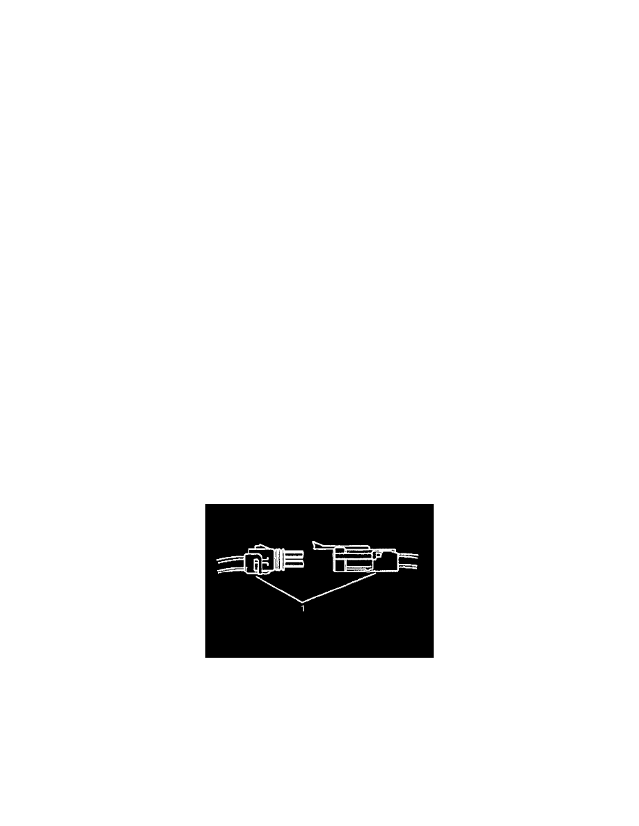
Follow the steps below in order to repair push to seat connectors.
1. Remove the Terminal Position Assurance (TPA) device, the Connector Position Assurance (CPA) device, and/or the secondary lock.
2. Separate the connector halves (1).