
Tracker 4WD L4-2.0L VIN C (1999)
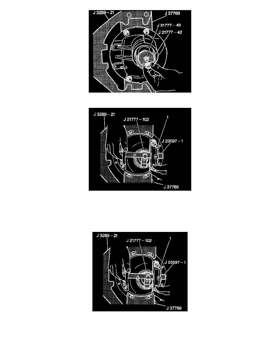
4. Place the outer pinion bearing into the differential carrier and install the J21777-102, the J 23597-12, the J 21777-43 and the J 21777-42.
Notice: Refer to Fastener Notice in Service Precautions.
5. Hold the J 21777-43 stationary.
^
Tighten the J 21777-43 jam nut to 2 Nm (18 inch lbs.).
6. Rotate J 21777-102 25 revolutions in order to ensure the pinion bearings (1) are fully seated.
^
Tighten the J 21777-43 jam nut to 2 Nm (18 inch lbs.).
7. Install the J21777-101 in the side bearing bores with the J 23597-1 through both of the J 21777-101.
8. Rotate the J21777-102 (1) until both gage levels are parallel with the J 21777-101.
9. Install the dial indicator spring loaded plunger extension through the J 23597-1 and position over the 97 mm level of the J 21777-102.
10. Install the J 8001 to the J 23597-1 and position the J 8001 plunger over the spring loaded plunger extension and slightly load the J 800 1.
11. Rotate the J 8001 adjustable face so that the needle indicates 0.
12. Slowly rotate the J 23597-1 back and forth so that the spring loaded plunger extension sweeps back and forth across the J 21777-102 while