
Tracker 4WD L4-2.0L VIN C (1999)
Important: If the original preload torque was less than 3 inch-pounds, reset the torque specification to 3-5 inch-pounds.
5. Measure the torque required to rotate the pinion. Compare this with the torque recorded earlier. Continue to tighten and measure a little at a time
until the same preload is achieved.
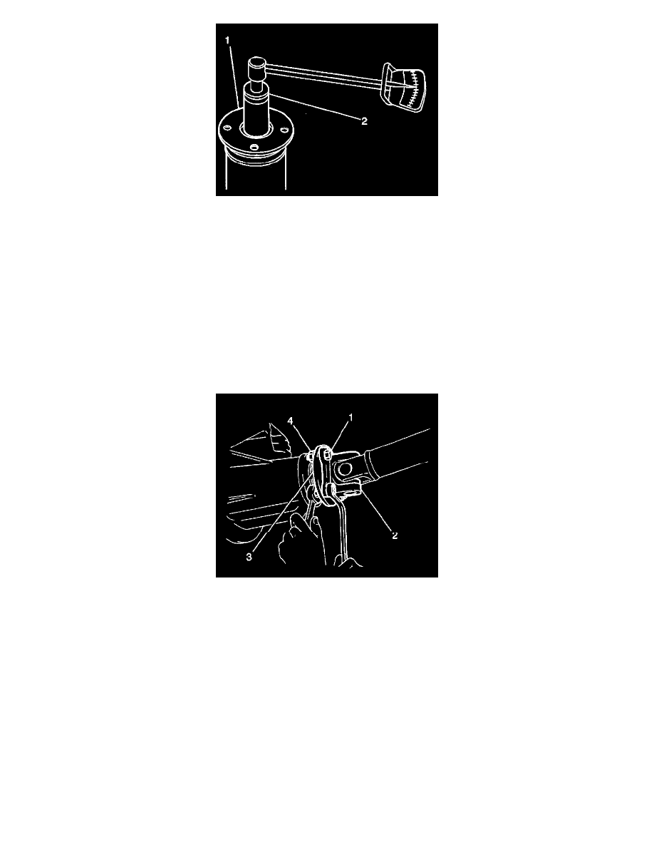
6. Align the propeller shaft with the alignment marks made previously. Use J 8614-01 in order to hold the pinion flange.
7. Install the propeller shaft to the pinion flange.
8. Install the bolts and retainers.
^
Tighten the bolts to 45 Nm (33 ft. lbs.).
Rear Drive Axle
Removal Procedure
^
Tools Required
-
J 8614-01 Companion Flange Holder
1. Remove the bolt and retainers.
Important: Observe and mark the positions of all the driveline components, relative to the propeller shaft and the axles, prior to disassembly. These
components include the propeller shafts, drive axles, pinion flanges, output shafts, etc. Reassemble all the components in the exact places in which you
removed the parts. Follow any specifications, torque values, and any measurements made prior to disassembly.
2. Mark the installed position of the propeller shaft and the pinion flange. Reassemble the propeller shaft and the pinion flange in the same position.
3. Remove the propeller shaft from the pinion flange.
3.1.
Use a piece of tape to hold the bearing caps.
3.2.
Secure the propeller shaft up and out of the way in order to not put any stress on the universal joints.
3.3.
Make an alignment mark on the pinion stem, pinion flange, and the pinion flange nut. Record the number of exposed threads on the pinion
stem for reference.
3.4.
Drain the axle fluid.