
TrailBlazer 2WD L6-4.2L VIN S (2003)
Steps 29-31
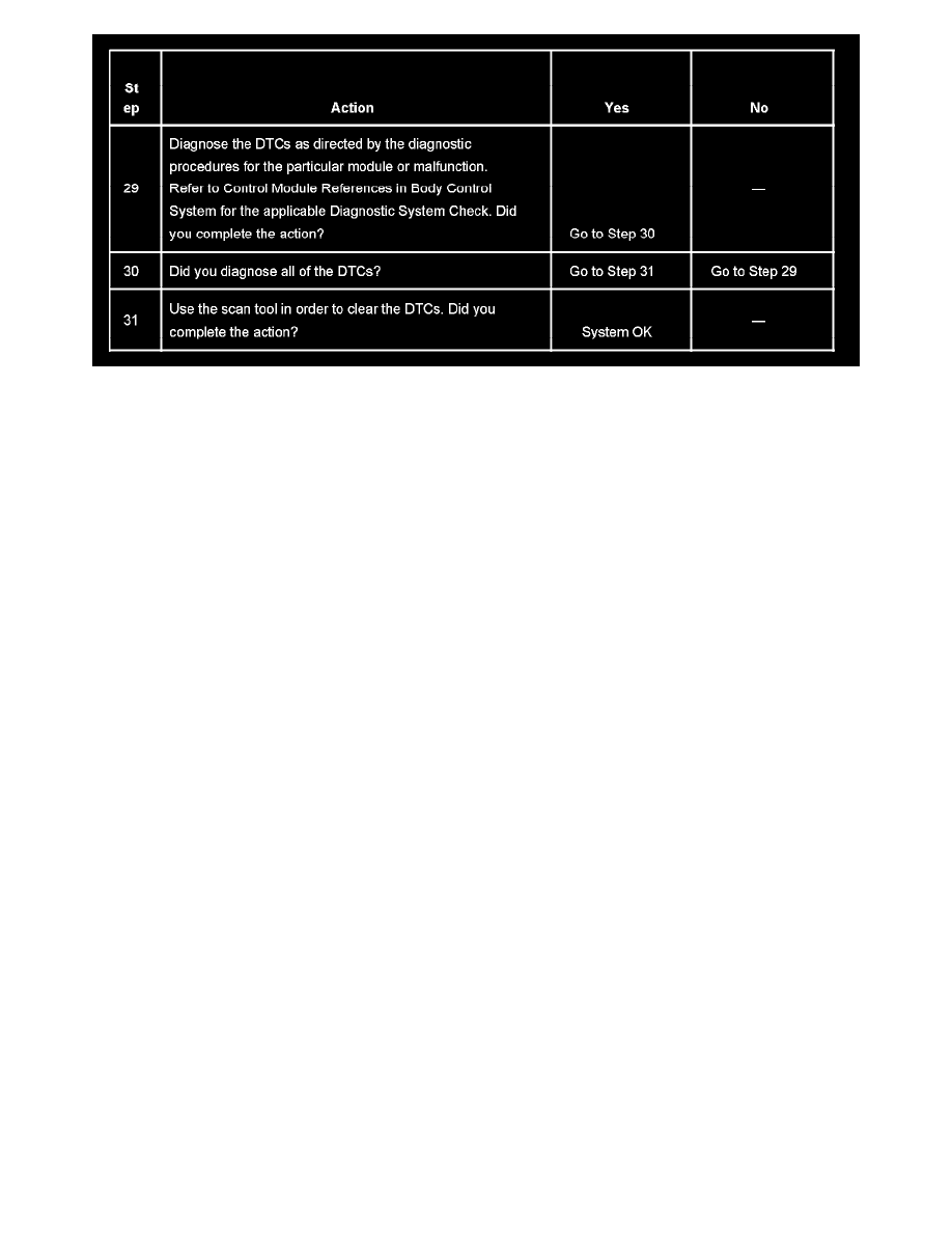
The numbers below refer to the step numbers on the diagnostic table.
2. A partial malfunction in the class 2 serial data circuit uses a different procedure from a total malfunction of the class 2 serial data circuit. The
following modules communicate on the class 2 serial data circuit:
3. The following DTCs may be retrieved with a history status, but are not the cause of the present condition.
-
U1300
-
U1301
-
U1305
6. A state of health DTC with a history status may be present along with a U1000 or U1255 code having a current status. This indicates that the
malfunction occurred when the ignition was ON.
7. Data link connector terminals 2 and 5 provide the connection to the class 2 serial data circuit and the signal ground circuit respectively.
10. A poor connection at DLC terminal of the splice pack SP205 would cause this condition but will not set a DTC.
11. This step may eliminate the loop created by PCM and theft deterrent module from failure cause.
12. An open in the class 2 serial data circuit between the DLC and splice pack SP205 will prevent the scan tool from communicating with any module.
This condition will not set a DTC.
14. The class 2 serial data circuit is shorted to voltage or ground. The condition may be due to the wiring or due to a malfunction in one of the
modules. When testing the wire for a short, make sure there is not a module connected to the wire being tested. This test isolates the BCM class 2
serial data circuits.
16. This test isolates the PCM class 2 serial data circuits.
18. The BCM detects that the ignition is ON and sends the appropriate power mode message to the other modules. Therefore, the BCM must remain
connected to the DLC for any other module to communicate with the scan tool. This test isolates the splice pack SP306 serial data circuits.
23. This test isolates the rest of the splice pack SP205 serial data circuits.
27. If there are no current DTCs that begin with a "U", the communication malfunction has been repaired.
28. The communication malfunction may have prevented diagnosis of the customer complaint.
Without Immobilizer
SCAN TOOL DOES NOT COMMUNICATE WITH CLASS 2 DEVICE (W/O IMMOBILIZER)
CIRCUIT DESCRIPTION
Modules connected to the class 2 serial data circuit monitor for serial data communications during normal vehicle operation. Operating information
and commands are exchanged among the modules. Connecting a scan tool to the DLC allows communication with the modules for diagnostic
purposes. DTCs may be set due to this symptom and during this diagnostic procedure. Complete the diagnostic procedure in order to ensure all the
DTCs are diagnosed and cleared from memory.
DIAGNOSTIC AIDS
-
The BCM detects that the ignition is ON and sends the appropriate power mode message to the other modules. Therefore, the BCM must be
connected to the DLC for any other module to communicate with the scan tool.
-
When the class 2 serial data circuit:
-
is shorted to ground
-
is shorted to voltage
The following DTCs may set:
-
U1300
-
U1301
-
U1305