
TrailBlazer 2WD V8-5.3L (2007)
Step 10 - Step 13
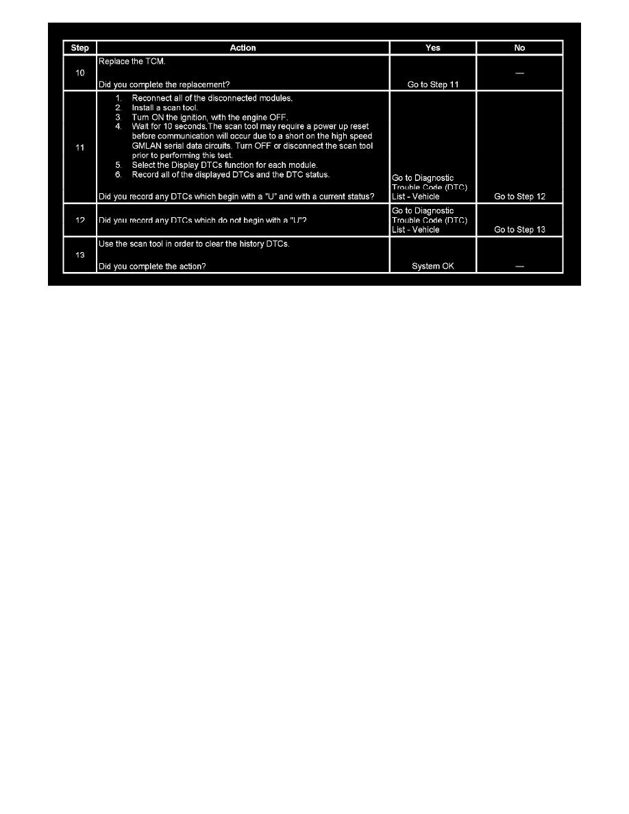
The numbers below refer to the step numbers on the diagnostic table.
2. A partial malfunction in the high speed GMLAN serial data circuits uses a different procedure from a total malfunction of the high speed GMLAN
data circuits. The following modules are connected to the high speed GMLAN serial data circuits:
-
ECM, for 5.3L
-
Transmission control module (TCM)
5. Data link connector terminals 6 and 14 provide the connection to the GMLAN serial data high circuit and the GMLAN serial data low circuit
respectively.
12. The communication malfunction may have prevented diagnosis of the customer complaint.
Scan Tool Does Not Power Up
SCAN TOOL DOES NOT POWER UP
CIRCUIT DESCRIPTION
The data link connector (DLC) is a standardized 16 cavity connector. Connector design and location is dictated by an industry wide standard, and is
required to provide the following:
-
Scan tool power battery positive voltage at terminal 16
-
Scan tool power ground at terminal 4
-
Common signal ground at terminal 5
The scan tool will power up with the ignition OFF. Some modules however, will not communicate unless the ignition is ON and the power mode
master (PMM) module sends the appropriate power mode message.
TEST DESCRIPTION