
TrailBlazer 2WD V8-6.0L VIN H (2006)
Ball Joint: Testing and Inspection
Ball Joint Inspection
Tools Required
^
J8001 Dial Indicator
1. Raise and support the vehicle.
Important:
^
The vehicle must rest on a level surface.
^
The vehicle must be stable. Do not rock the vehicle on the floor stands.
^
The upper control arm bumper must not contact the frame.
2. Support the lower control arm with a floor stand or jack, as far outboard as possible.
3. Clean and inspect the ball joint seals for cuts or tears. If the ball joint seals are damaged, replace the ball joint. Refer to Lower Ball Joint
Replacement or Upper Control Arm Replacement.
Important: If a seal is cut or torn, replace the ball joint.
4. Check the wheel bearing for looseness. If looseness in the wheel bearing is present,
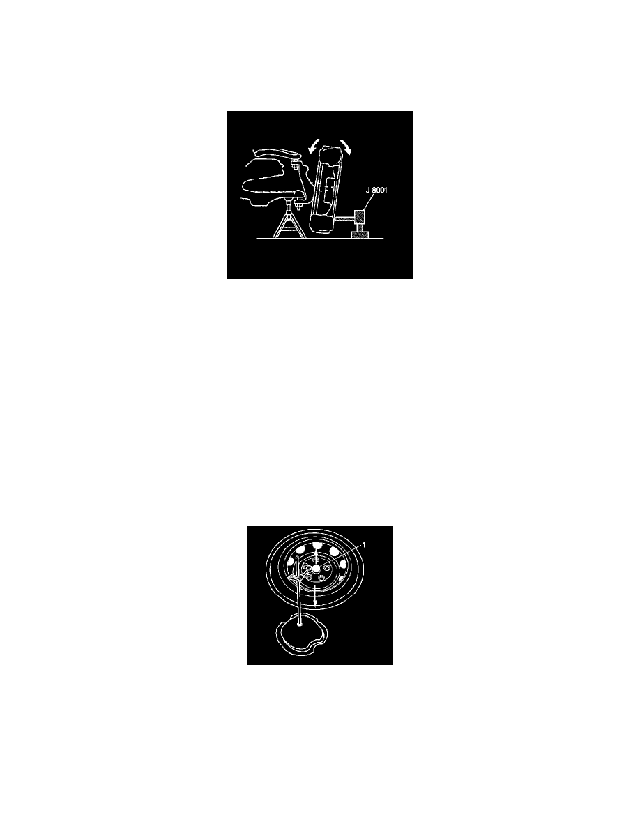
5. Check the ball joints for horizontal looseness.
1. Position the J8001 against the lowest outboard point on the wheel rim.
2. Rock the wheel in and out while reading the dial indicator. This shows horizontal looseness in both joints.
3. The dial indicator reading should be no more than 2 mm (0.080 inch). If the reading is too high, check the lower ball joints for vertical
looseness.
6. For 4WD vehicles, place a J8001 (1) against the spindle in order to show vertical movement.
Notice: Do not pry between the lower arm and the wheel drive shaft boot or in such a manner that the ball joint seal is contacted. Damage to the
wheel drive shaft boot will result (4WD).