
Traverse FWD V6-3.6L (2009)
Check - Vehicle) prior to using this diagnostic procedure.
*
Review Strategy Based Diagnosis (See: Testing and Inspection/Initial Inspection and Diagnostic Overview/Strategy Based Diagnosis) for an
overview of the diagnostic approach.
*
Diagnostic Procedure Instructions (See: Testing and Inspection/Initial Inspection and Diagnostic Overview/Diagnostic Procedure Instructions
)provides an overview of each diagnostic category.
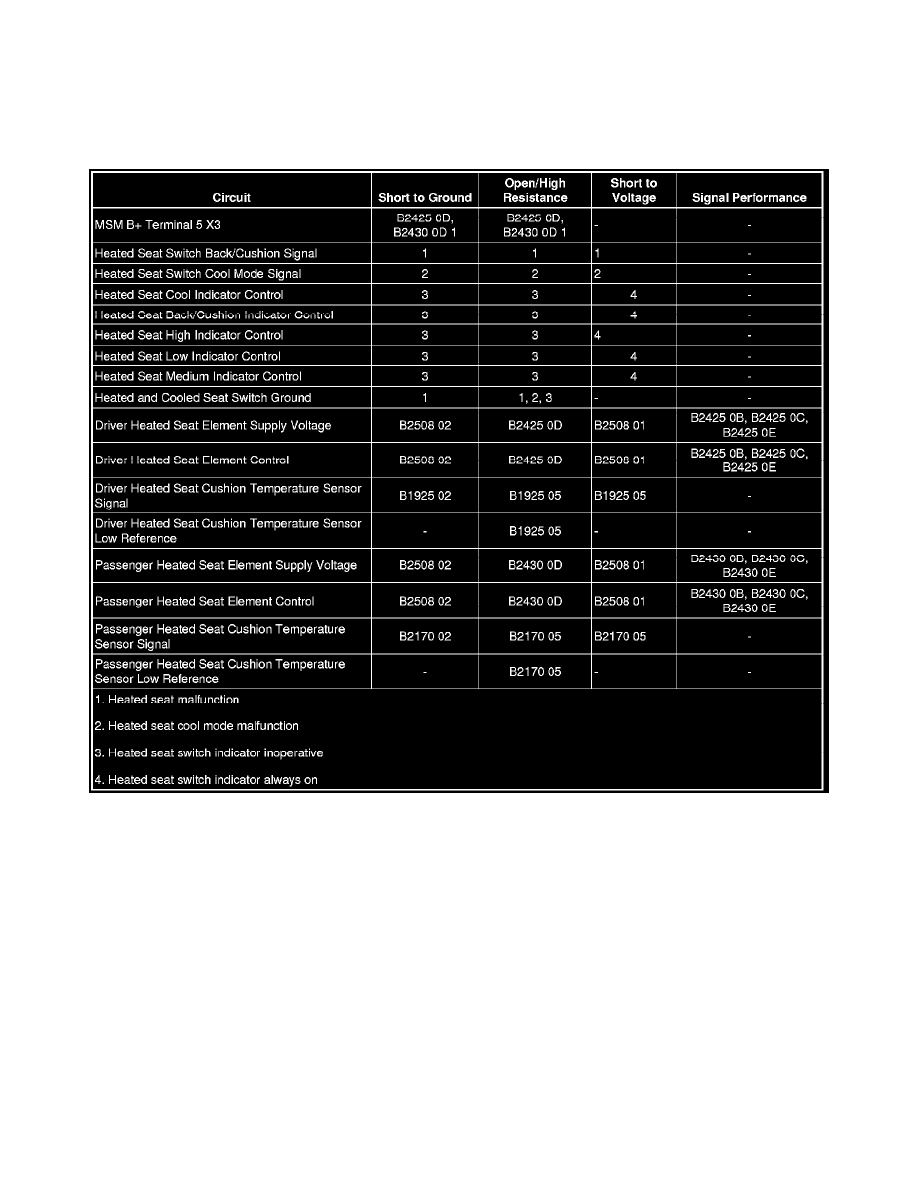
Diagnostic Fault Information
Circuit/System Description
The driver and front passenger heated seats are controlled by separate heated seat switches. When a heated seat switch is pressed, ground is momentarily
applied through the switch contacts and the switch signal circuit to the door module. In response to this signal, the door module sends serial data a
message to the memory seat module (MSM) indicating the heat seat request. The door module then applies voltage through the appropriate indicator
control circuits to the heated seat switch illuminating the indicators.
Reference Information
Schematic Reference
Heated/Cooled Seat Schematics (Except A45) (See: Diagrams/Electrical Diagrams/Except A45)Heated/Cooled Seat Schematics (A45 with KA1) (
See: Diagrams/Electrical Diagrams/A45 with KA1)Heated/Cooled Seat Schematics (A45 with KB6) (See: Diagrams/Electrical Diagrams/A45 with
KB6)
Connector End View Reference
Component Connector End Views (See: Diagrams/Connector Views)
Description and Operation
Heated Seats Description and Operation (See: Description and Operation/Heated Seats Description and Operation)
Electrical Information Reference