
Traverse FWD V6-3.6L (2009)
Circuit/System Description
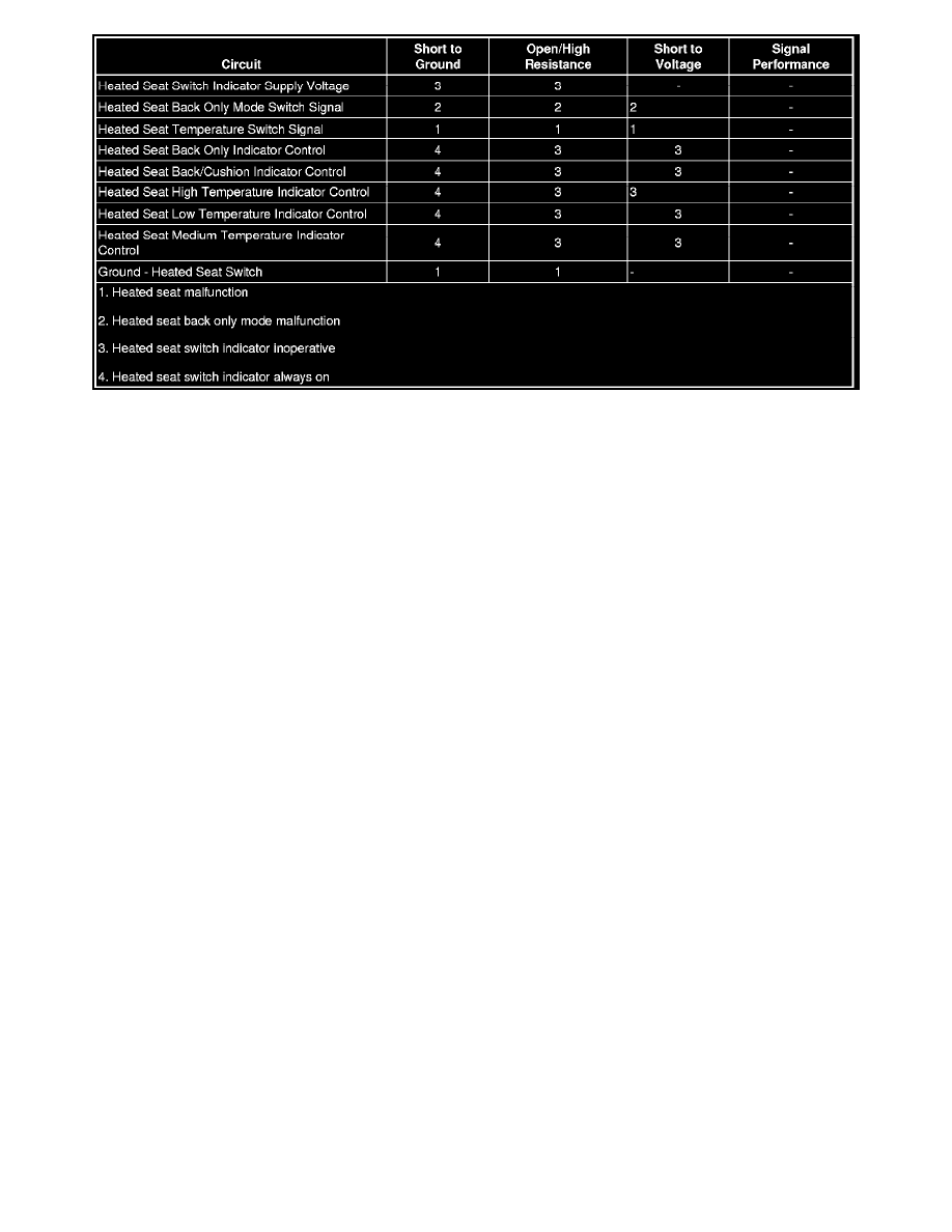
The driver and front passenger heated seats are controlled by separate heated seat switches. When a heated seat switch is pressed, ground is momentarily
applied through the switch contacts and the switch signal circuit to the heated seat module (HSM). In response to this signal, the module then applies
battery voltage through the element supply voltage circuits to the seat cushion and seat back heating elements. The HSM then supplies a ground through
the appropriate indicator control circuits to the heated seat switch illuminating the switch indicators.
Reference Information
Schematic Reference
Heated/Cooled Seat Schematics (Except A45) (See: Diagrams/Electrical Diagrams/Except A45)Heated/Cooled Seat Schematics (A45 with KA1) (
See: Diagrams/Electrical Diagrams/A45 with KA1)Heated/Cooled Seat Schematics (A45 with KB6) (See: Diagrams/Electrical Diagrams/A45 with
KB6)
Connector End View Reference
Component Connector End Views (See: Diagrams/Connector Views)
Description and Operation
Heated Seats Description and Operation (See: Description and Operation/Heated Seats Description and Operation)
Electrical Information Reference
*
Circuit Testing (See: Testing and Inspection/Component Tests and General Diagnostics)
*
Connector Repairs (See: Testing and Inspection/Component Tests and General Diagnostics)
*
Testing for Intermittent Conditions and Poor Connections (See: Testing and Inspection/Component Tests and General Diagnostics)
*
Wiring Repairs (See: Testing and Inspection/Component Tests and General Diagnostics)
Scan Tool Reference
Control Module References (See: Testing and Inspection/Programming and Relearning) for scan tool information
Circuit/System Verification
1. Ignition ON, observe the appropriate scan tool Heated Seat Module parameter listed below while pressing and releasing the heated seat back and
cushion switch. The readings should change between Off and Back and Cushion.
*
Driver Seat HVC Mode
*
Passenger Seat HVC Mode
‹› If not the specified value, refer to Heated Seat Switch Malfunction.
2. Ignition ON, observe the appropriate scan tool Heated Seat Module parameter listed below while pressing and releasing the heated seat back only
switch. The readings should change between Off and Back Only.
*
Driver Seat HVC Mode