
Traverse FWD V6-3.6L (2009)
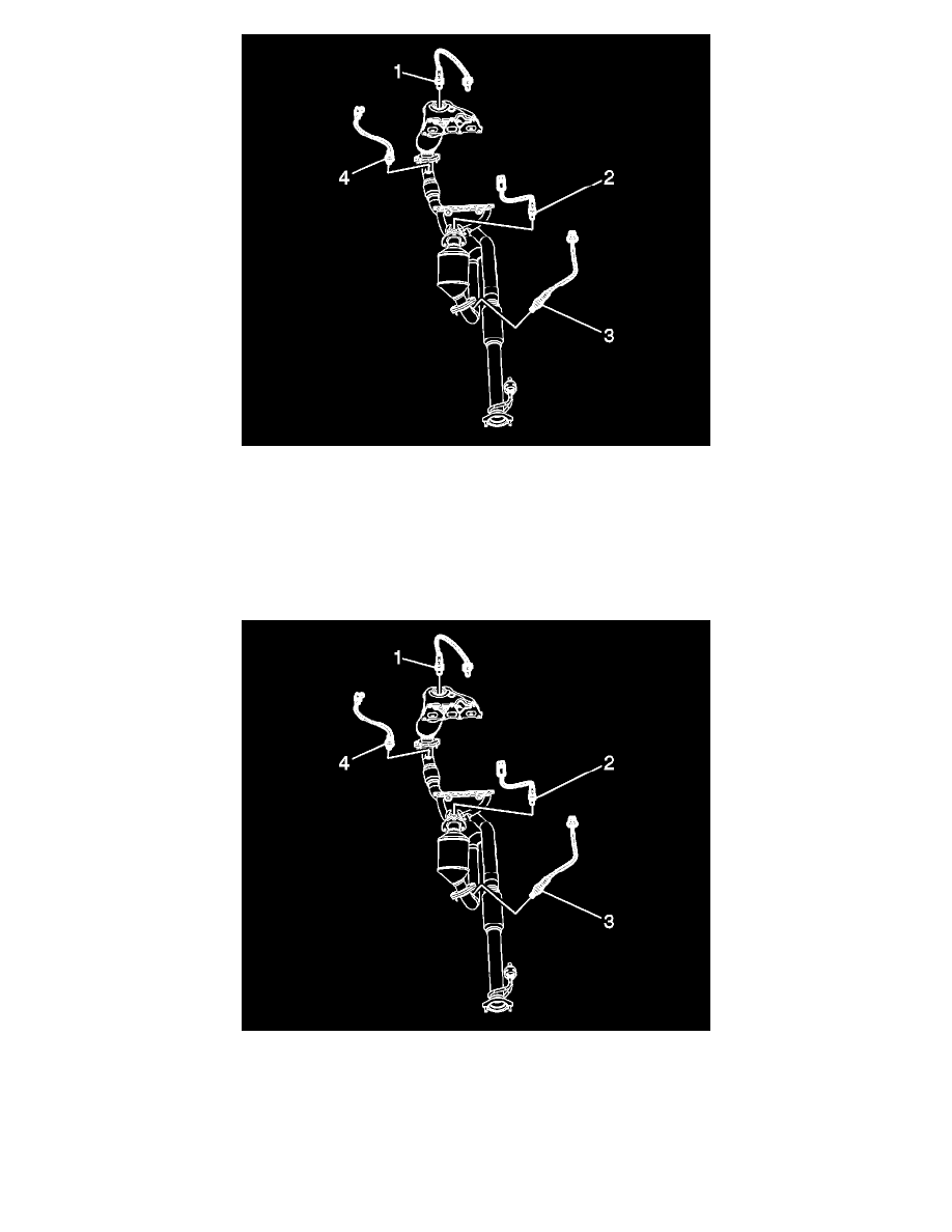
6. Remove the heated oxygen sensor (1) from the exhaust manifold.
Installation Procedure
Note: A special anti-seize compound is used in the HO2S threads. The compound consists of liquid graphite and glass beads. The graphite tends to burn
away, but the glass beads remain, making the sensor easier to remove. New, or service replacement sensors have the compound applied to the threads. If
the sensor is removed from an exhaust component and if for any reason the sensor is to be reinstalled, the threads must have anti-seize compound applied
before the reinstallation.
1. If reinstalling the old sensor, coat the threads with anti-seize compound GM P/N 12377953, or equivalent.
Caution: Refer to Fastener Caution (See: Service Precautions/Vehicle Damage Warnings/Fastener Caution).
2. Install the HO2S (1) to the exhaust manifold.
Tighten the sensor to 42 Nm (31 lb ft).