
Uplander FWD V6-3.5L VIN L (2006)
1. Rotate the brake rotor to position the high spot, identified and marked during the brake rotor assembled LRO measurement procedure, to face
upward.
2. Remove the J 45101-100 and the lug nuts that were installed during the assembled LRO measurement procedure and/or the indexing correction
procedure.
3. Inspect the mounting surface of the hub/axle flange and the brake rotor to ensure that there are no foreign particles or debris remaining.
4. Select the correction plate, following the manufacturer's instructions, which has a specification closest to the assembled LRO measurement .For
example: If the assembled LRO measurement was 0.076 mm (0.003 inch), the 0.076 mm (0.003 inch) correction plate would be used. If the
measurement was 0.127 mm (0.005 inch), the 0.152 mm (0.006 inch) correction plate would be used.
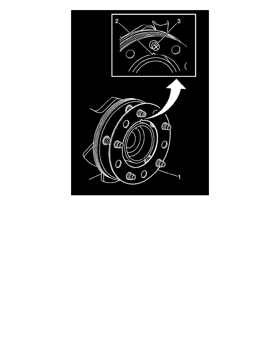
5. Determine the positioning for the correction plate (1) using the high spot mark (3) made during the brake rotor assembled LRO measurement
procedure.
6. Important:
^
Do NOT install used correction plates in an attempt to correct brake rotor assembled lateral runout (LRO).
^
Do NOT stack up, or install more than one correction plate onto one hub/axle flange location, in an attempt to correct brake rotor assembled
LRO.
Install the correction plate (1) onto the hub/axle flange, with the V-shaped notch (2) orientated to align with the high spot mark (3), that was
positioned to face upward.