
Venture V6-3.4L VIN E (1997)
Backup Lamp: Initial Inspection and Diagnostic Overview
Circuit Operation
Voltage is applied through the B/U LAMP Fuse to the transaxle range switch through circuit 840. When the shift selector is placed in REVERSE,
voltage is applied through the transaxle range switch, to the RH and LH backup lamps through circuit 24. The backup lamps are grounded through circuit
350 to G401, and when voltage is applied to circuit 24, the backup lamps are ON.
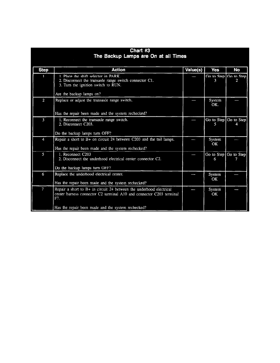
Chart #3 The Backup Lamps Are ON At All Times