
Volt L4-1.4L Elect (2011)
Front Subframe: Service and Repair
Drivetrain and Front Suspension Frame Replacement
Removal Procedure
1. Disable the high voltage system. Refer to High Voltage Disabling .
2. Disconnect the negative battery cable from the battery. Refer to Battery Negative Cable Disconnection and Connection .
Caution: With wheels of the vehicle facing straight ahead, secure the steering wheel utilizing steering column anti-rotation pin, steering column
lock, or a strap to prevent rotation. Locking of the steering column will prevent damage and a possible malfunction of the SIR system. The steering
wheel must be secured in position before disconnecting the following components:
*
The steering column
*
The intermediate shaft(s)
*
The steering gear
After disconnecting these components, do not rotate the steering wheel or move the front tires and wheels. Failure to follow this procedure may
cause the SIR coil assembly to become un-centered and cause possible damage to the SIR coil. If you think the SIR coil has became un-centered,
refer to your specific SIR coil's centering procedure to re-center SIR Coil.
3. Support the radiator and condenser from above using the condenser tabs on each side.
4. Remove the front bumper fascia. Refer to Front Bumper Fascia Removal and Installation (See: Body and Frame/Bumper/Front Bumper/Front
Bumper Cover / Fascia/Service and Repair/Front Bumper Fascia Removal and Installation).
5. Install the engine support fixture. Refer to Engine Support Fixture .
6. Remove the lower steering intermediate shaft bolt. Refer to Intermediate Steering Shaft Replacement .
Danger: Do not use a service jack to lift this vehicle. Lifting the vehicle with a jack could cause the vehicle to slip off the jack and roll; this
could cause injury or death.
7. Raise the vehicle on a hoist. Refer to Lifting and Jacking the Vehicle .
8. Remove the front tire and wheel assemblies. Refer to Tire and Wheel Removal and Installation .
9. Remove the catalytic converter. Refer to Catalytic Converter Replacement .
10. Remove the front wheelhouse liner. Refer to Front Wheelhouse Rear Liner Replacement (See: Body and Frame/Fender/Front Fender/Front
Fender Liner/Service and Repair/Front Wheelhouse Rear Liner Replacement).
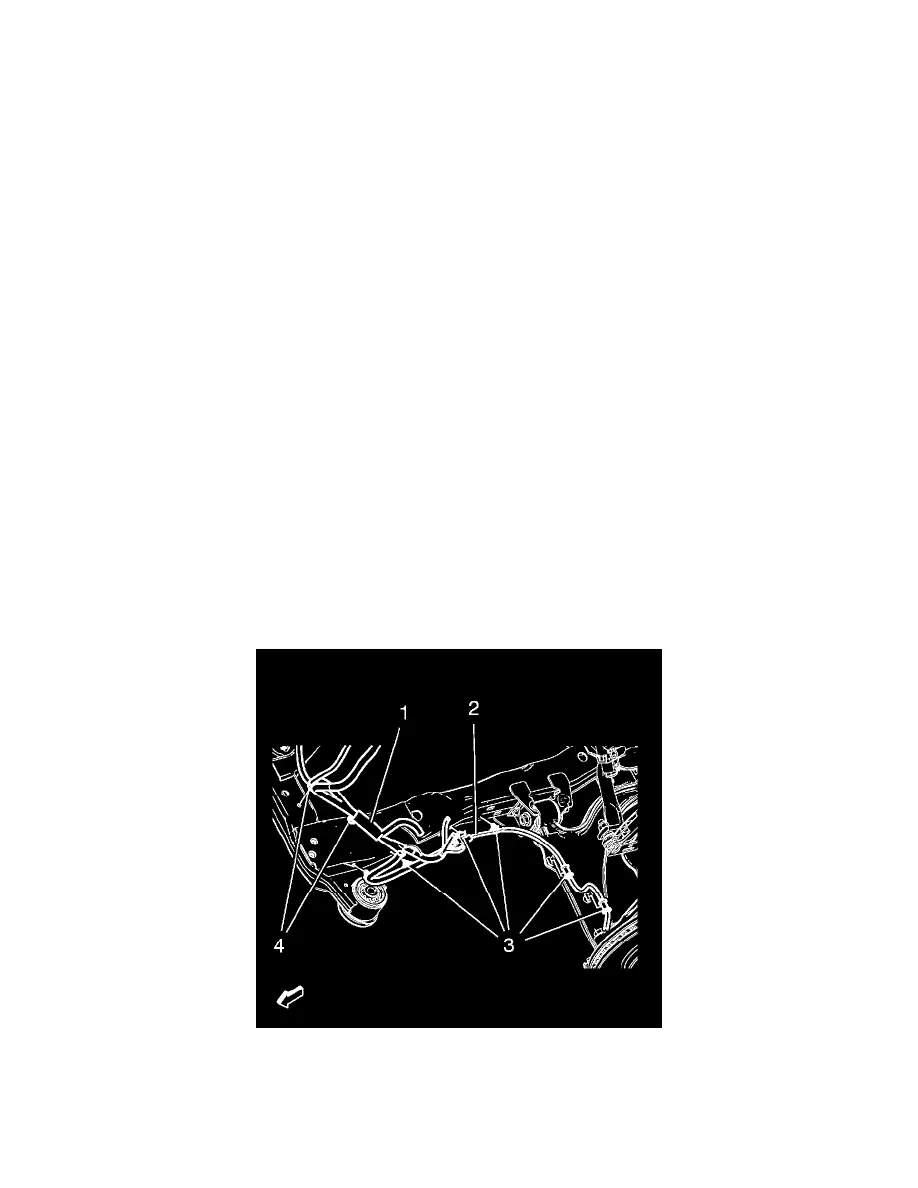
11. Remove the wheel speed sensor wiring harness (2) from the frame on both sides.
Remove the wiring harness retainers (3) from the frame and the lower control arm.
12. Remove the heater inlet and outlet pipe bolts from frame. Refer to Heater Inlet And Outlet Pipe Replacement .
13. Position the heater water auxiliary pump and support to the side. Refer to Heater Water Auxiliary Pump Replacement .
Caution: Electrostatic discharge (ESD) can damage many solid-state electrical components. ESD susceptible components may or may not be