
Concorde V6-2.7L VIN R (1998)
2. Necking can be checked by holding a scale or straight edge against the threads. If all the threads do not contact the scale the bolt should be
replaced.
3. Before installing the bolts, lubricate the threads with engine oil.
4. Install bolts finger tight then alternately torque each nut to assemble the cap properly.
5. Tighten the nuts to 27 Nm PLUS 1/4 turn (20 ft. lbs. PLUS 1/4 turn).
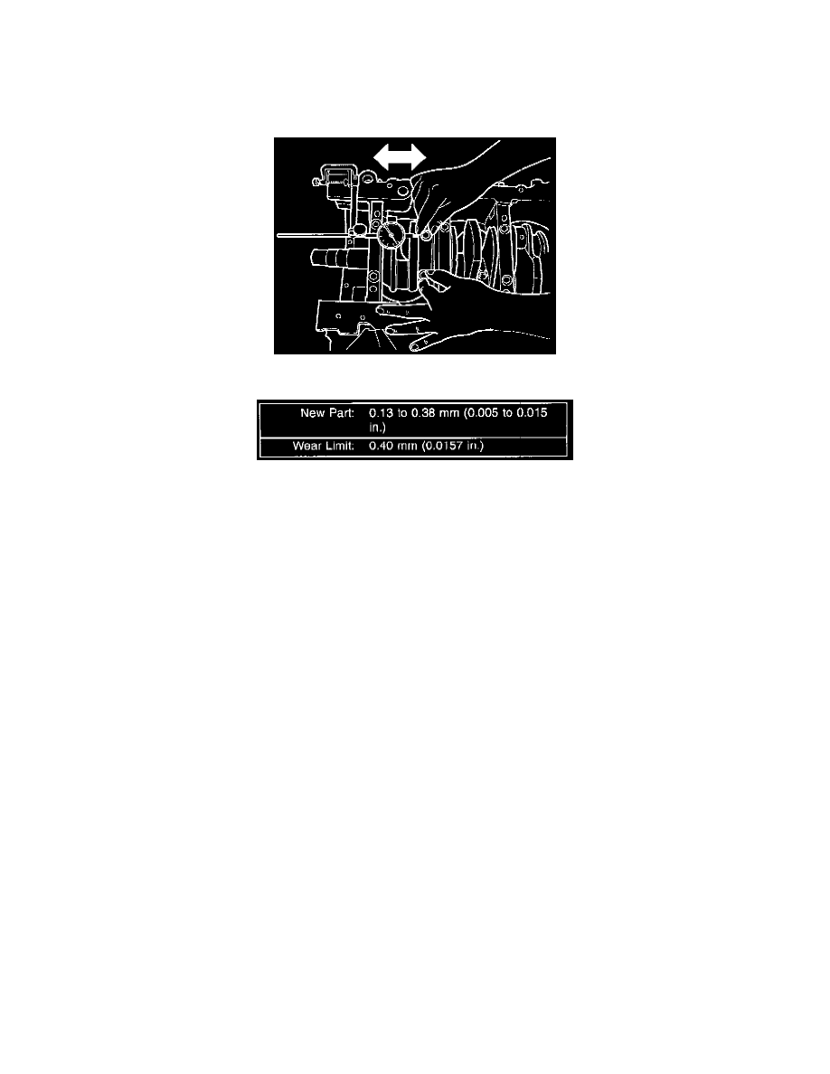
Figure 14-Connecting Rod Side Clearance Measuring
Connecting Rod Side Clearance Chart
6. Mount a dial indicator to a stationary point on engine. Locate probe perpendicular to and resting against the connecting rod cap being checked.
Move connecting rod all the way to rear of its travel. Zero the dial indicator. Move connecting rod forward to limit of travel and read the dial
indicator. Repeat procedure for each connecting rod. Turn crankshaft for connecting rod accessibility.