
Concorde V6-2.7L VIN V (2001)
Each module on the PCI bus has a small termination load of a parallel resistance and capacitor to make up part of the over all bus termination load.
One or two modules on the PCI bus may have a higher load termination to provide stabilizing influence over the variations of vehicle builds.
These modules, called dominant modules, may very for car line to car line. The Powertrain Control Module (PCM) is the only dominant node for
this vehicle.
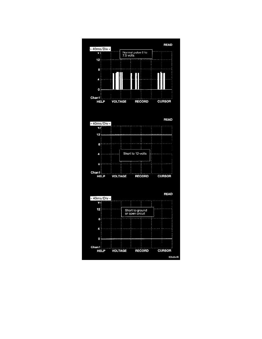
Each module provides its own bias and termination in order to transmit and receive messages. The bus voltage is at zero volts when no modules
are transmitting and is pulled up to about seven and a half volts when modules are transmitting. The bus messages are transmitted at a rate
averaging 10800 bits per second. Since there is only voltage present when the modules transmit, and the message length is only about 500
milliseconds, it is ineffective to try and measure the bus activity with a conventional voltmeter. The preferred method is to use DRBIII(R) lab
scope. The 12 V square wave selection on the 20-volt scale provides a good view of the bus activity. Voltage on the bus should pulse between
zero and about seven and a half volts. Refer to the following figure for some typical displays.
The PCI Bus failure modes are broken down into two categories. PCI Bus Communication Failure and individual module no response. Causes of a
PCI Bus communication failure include a short to ground or to voltage on any PCI Bus circuit. Individual module no response can be caused by an
open circuit at the BCM or at the module, or an open battery or ground circuit to the affected module.
Symptoms of a complete PCI Bus communications failure would include but are not limited to:
-
All gauges on the MIC stay at zero