
Concorde V6-2.7L VIN V (2001)
Connecting Rod Bearing: Service and Repair
STANDARD PROCEDURES - CONNECTING ROD AND BEARING FITTING
CONNECTING ROD BEARING
Fit all connecting rods on one bank until complete.
The bearing caps are not interchangeable and should be marked at removal to ensure correct assembly.
CAUTION: Care must be taken not to damage the fractured rod and cap joint face surfaces as engine damage may occur.
The bearing shells must be installed with the tangs inserted into the machined grooves in the rods and caps. Also, assure that the hole in upper bearing
half aligns with oil squirt hole in rod. Install cap with the tangs on the same side as the rod.
CAUTION: Assure that hole in upper bearing half aligns with hole in connecting rod as engine damage may occur.
Limits of taper or out-of-round on any crankshaft journals should be held to 0.015 mm (0.0006 inch). Bearings are available 0.025 mm (0.001 inch)
and 0.250 mm (0.010 inch) undersize. Install the bearings in pairs. Do not use a new bearing half with an old bearing half. Do not file the rods or
bearing caps.
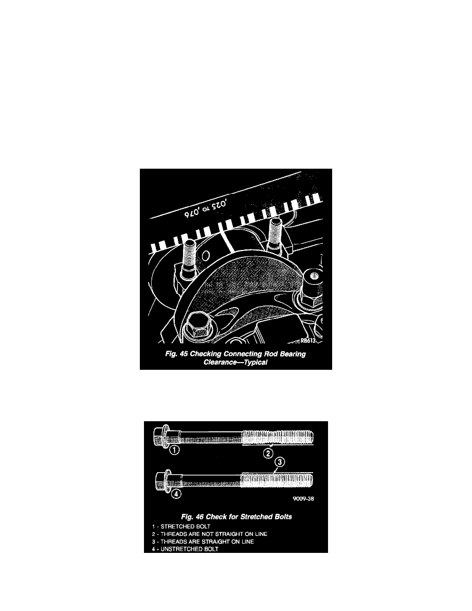
1. For measuring Main Bearing Clearance and Connecting Rod Bearing Clearance use plastigage (Fig. 45). Refer to Engine Specifications for
bearing clearance specifications.
CONNECTING ROD BOLTS
NOTE: The connecting rod bearing cap bolts must be examined before reuse. If the threads are necked down due to stretching, the bolt(s) must be
replaced (Fig. 46). Connecting rod bolts are retained in the rod cap with a light press fit. If bolts are to be removed, use a hammer and punch to drive
bolts from connecting rod cap using care not to damage fractured cap surface.