
Concorde V6-2.7L VIN V (2001)
CAUTION: USE SUPPLIED SCREWS ONLY.
2. Tighten the top screw on the drivers side.
3. Install the two side module mounting screws on the drivers side.
4. Connect ORC 23-way connector and slide the red Connector Position Assurance (CPA) tab in.
NOTE: If working on a Concorde, the Instrument Panel must be installed. Refer to Body, Instrument Panel for Installation and then go to
Electrical, Restraints, Diagnosis and Testing - Airbag System.
5. Install left console side panel and two retaining screws.
6. Install the right console side panel.
7. Install the screws in the upper and lower left corner or the glove box bin.
8. Close the glove box door.
9. Install the steering wheel cover and the two screws to steering column cover.
10. Install the left instrument panel end cover covering the junction block.
11. Connect power outlet connector and install the center bezel into vehicle.
12. Install the two screws to shifter bezel.
13. Install the one screw to shift knob.
WARNING: DO NOT CONNECT THE BATTERY NEGATIVE CABLE REMOTE TERMINAL. REFER TO ELECTRICAL,
RESTRAINTS, DIAGNOSIS AND TESTING - AIRBAG SYSTEM FIRST.
Six Passenger Vehicle Replacement
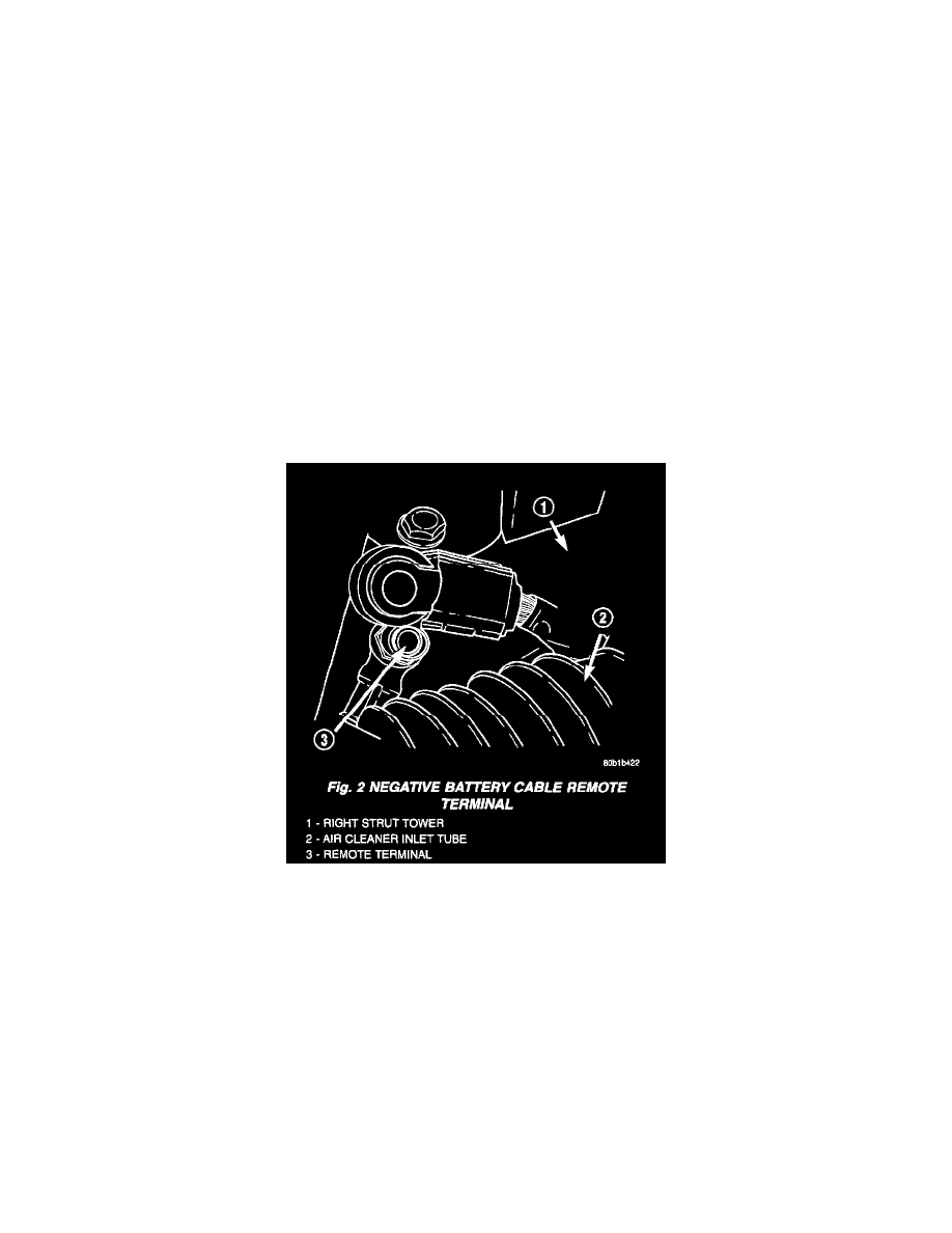
Fig.2 Negative Battery Cable Remote Terminal
REMOVAL
1. Open hood and disconnect the negative battery cable remote terminal from the remote battery post.
2. Open glove box door and release side tabs and swing down.
NOTE: If working on a Concorde, the Instrument Panel must be removed. Refer to Body, Instrument Panel, for Removal. Then go to Step 10.
3. Remove the left endcap at the junction block.
4. Remove two screws to steering column cover then pull toward rear of vehicle to disengage clips.
5. Open glove box door. Continue to pull down on the door until the glove box drops and you see the screws in the upper and lower left corner or the
glove box bin.
6. Remove the instrument panel center bezel. The temperature control module, power outlet and traction control switch will pop out with the center
bezel.
7. Disconnect the connectors at center bezel.
8. Remove four screws to Chin bezel. Two on the right side and two on the left side of vehicle.
9. Remove one screw and one push fastener retaining floor bin.