
Concorde V6-2.7L VIN V (2001)
Remote Switch: Testing and Inspection
WARNING: ON VEHICLES EQUIPPED WITH AIRBAGS, REFER TO ELECTRICAL, RESTRAINT SYSTEMS BEFORE ATTEMPTING
ANY STEERING WHEEL, STEERING COLUMN, OR INSTRUMENT PANEL COMPONENT DIAGNOSIS OR SERVICE. FAILURE TO
TAKE THE PROPER PRECAUTIONS COULD RESULT IN ACCIDENTAL AIRBAG DEPLOYMENT AND POSSIBLE PERSONAL
INJURY.
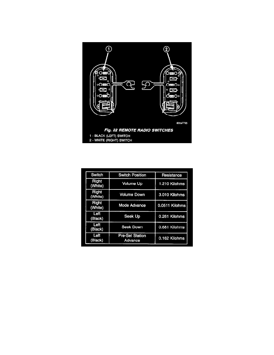
Fig.22 Remote Radio Switches
1. Disconnect and isolate the battery negative cable Remove the remote radio switch(es) from the steering wheel.
Remote Radio Switch Test
2. Use an ohmmeter to check the switch resistances as shown in the Remote Radio Switch Test table. If the remote radio switch resistances check
OK, go to Step 3. If not OK, replace the faulty switch.
3. Reconnect the battery negative cable. Turn the ignition switch to the ON position. Check for 5 volts at the radio control mux circuit cavities of the
steering wheel wire harness connectors for both remote radio switches. If OK, go to Step 4. If not OK, repair the open or shorted radio control
mux circuit to the Body Control Module (BCM) as required.
4. Disconnect and isolate the battery negative cable. Disconnect the 22-way instrument panel wire harness connector from the BCM. Check for
continuity between the remote radio switch ground circuit cavities of the steering wheel wire harness connectors for both remote radio switches
and a good ground. There should be no continuity. If OK, go to Step 5. If not OK, repair the shorted remote radio switch ground circuit to the
BCM as required.
5. Check for continuity between the remote radio switch ground circuit cavities of the steering wheel wire harness connectors for both remote radio
switches and the 22-way instrument panel wire harness connector for the BCM. There should be continuity. If OK, refer to the proper Body
Diagnostic Procedures to test the BCM and the PCI data bus. If not OK, repair the open remote radio switch ground circuit as required.