
Concorde V6-3.5L VIN V (2003)
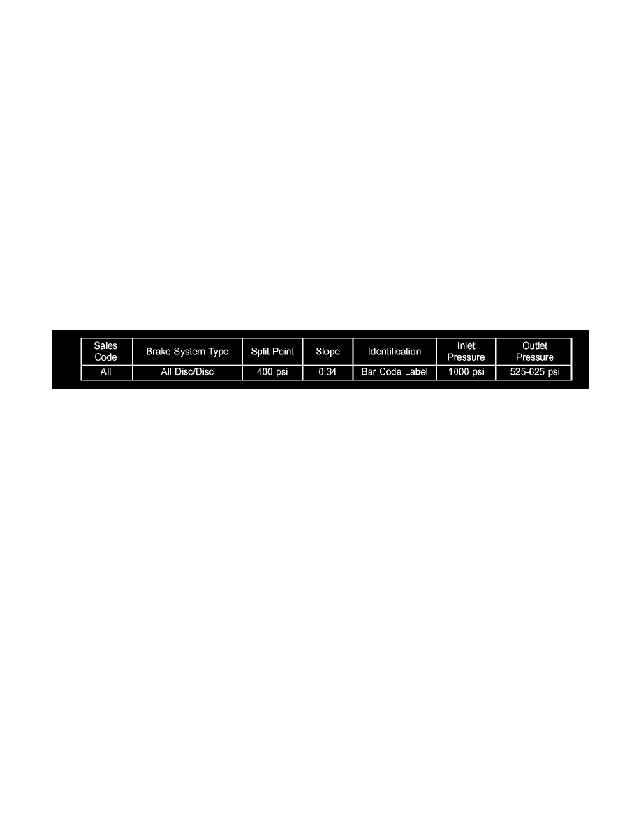
to rear brake). If proportioning valve outlet pressure does not agree with value shown on the chart (once inlet pressure shown on chart is obtained),
replace the junction block (with internal proportioning valves). If pressure is within specifications, do not replace proportioning valve and perform
the following steps.
18. Remove the Pressure Gauge and Adapter, Special Tool 8494-3 or 8494-4, from junction block.
19. Reinstall the chassis brake tube to the junction block port. Tighten tube nut fitting to 17 Nm (145 inch lbs.) torque.
20. Install the transmission control module (with speed control servo attached) in its normal position. Install the nut and screw securing it in place.
21. Install the transmission control module mounting nut and screw securing it in place. Tighten the screw to 6 Nm (45 inch lbs.). Tighten the nut to
12 Nm (107 inch lbs.) torque.
22. Install the screw attaching the washer filler tube to the upper radiator closure panel.
23. Install the screw attaching the speed control servo to the upper radiator closure panel.
24. Remove the Pressure Gauge and Adapter from master cylinder.
25. Install the brake tube to the master cylinder primary or secondary port. Tighten the tube nut to a torque of 17 Nm (145 inch lbs.).
26. Bleed the affected brake line.
27. If no problem is found with the proportioning valves, check the rear wheel brake shoe linings for contamination or for replacement brake shoes not
meeting OEM brake lining material specifications. These conditions can also cause premature rear wheel skid.
PROPORTIONING VALVE APPLICATIONS AND PRESSURE SPECIFICATIONS