
Crossfire V6-3.2L VIN L (2004)
Air Bag: Description and Operation
Passenger Airbag
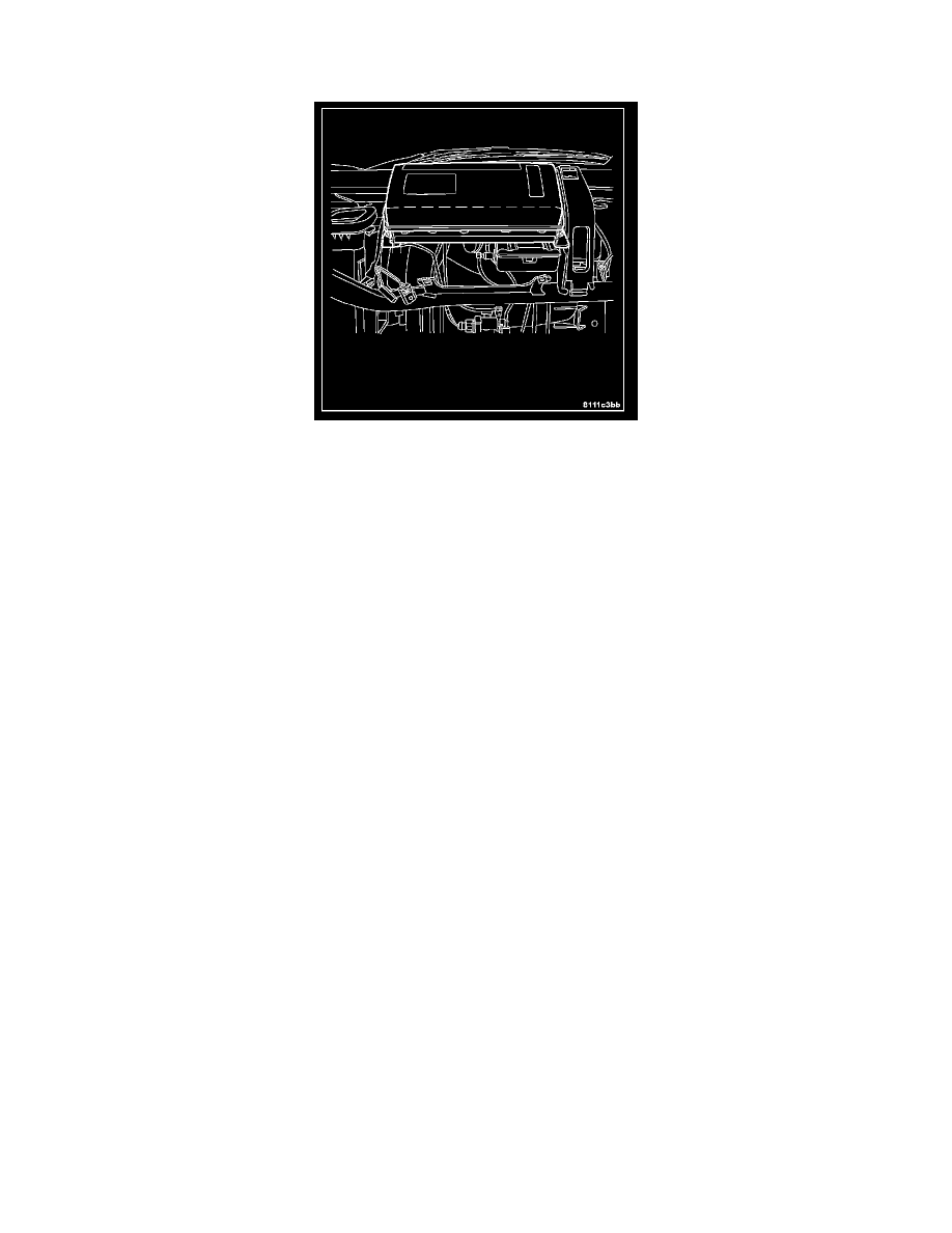
The surface of the instrument panel top pad above the glove box is the most visible part of the passenger airbag. The passenger airbag door is concealed
behind the instrument panel top pad and above the glove box opening on the instrument panel in front of the front seat passenger seating position.
The passenger airbag unit used in this model is a multistage, Next Generation-type that complies with revised federal airbag standards to deploy with less
force than those used in some prior models. The passenger airbag unit consists of an extruded aluminum housing, two stamped steel end brackets, a
molded plastic inner airbag cushion cover, the rectangular fabric airbag cushion, and the airbag inflator. The airbag housing contains the airbag inflator,
while the inner cover contains the folded airbag cushion. The inner cover completely encloses the airbag cushion and is permanently retained to the
housing. The airbag cushion is constructed of a coated nylon fabric. The airbag inflator is a dual-initiator, hybrid-type unit that is secured to and sealed
within the airbag housing.
NOTE: The passenger airbag cannot be repaired, and must be replaced if deployed, faulty, or in any way damaged. The passenger airbag door is
serviced only as a unit with the instrument panel top pad. If the passenger airbag is deployed, the instrument panel top pad must also be replaced. If
inspection reveals that the passenger airbag mounting points on the instrument panel structural duct have been cracked or damaged by the deployment
event, the instrument panel structural duct assembly must also be replaced.
The multistage passenger airbag is deployed by electrical signals generated by the Occupant Restraint Controller (ORC) through the passenger airbag
squib 1 and squib 2 circuits to the two initiators in the airbag inflator. By using two initiators, the airbag can be deployed at multiple levels offeree. The
force level is controlled by the ORC to suit the monitored impact conditions by providing one of four delay intervals between the electrical signals
provided to the two initiators. The longer the delay between these signals, the less forcefully the airbag will deploy.
AIRBAG DEPLOYMENT SEQUENCE
1. When the impact threshold for the passenger airbag is exceeded an electric pulse (firing pulse) is sent from the ORC to the squib in the initiator.
2. The squib ignites the solid propellant in the initiator. The solid propellant burns, developing a gas which flows explosively under high pressure
into the airbag.
3. Under the pressure of the gas, the airbag rips open the airbag housing, blows the airbag flap out of the instrument panel and inflates in the
passenger compartment.
4. After approximately 50 ms. the airbag reaches its maximum volume.
5. After reaching the maximum volume, the pressure in the airbag starts decreasing. The gas escapes from the airbag through a filter and the airbag
deflates.
NOTE: Typically, both initiators are used during an airbag deployment event. However, it is possible for only one initiator to be used during a
deployment due to an airbag system fault; therefore, it is necessary to always confirm that both initiators have been used in order to avoid the improper
disposal of potentially live pyrotechnic materials.