
Pacifica V6-3.8L VIN L (2005)
Solar Sensor: Service and Repair
REMOVAL
1. Open the liftgate.
2. Disconnect and isolate the negative battery cable.
3. Remove the left rear D-pillar trim panel from the vehicle.
CAUTION: Locate the wires coming from the optical sensor. On a piece of paper, note the wire location and cavity the wires are currently
installed in on both the sensor and connector side of the harness. This will prove helpful later.
4. Cut the wires leading to the optical sensor and back the wires out of the drive unit's main electrical connector. Refer to the Wiring for instructions.
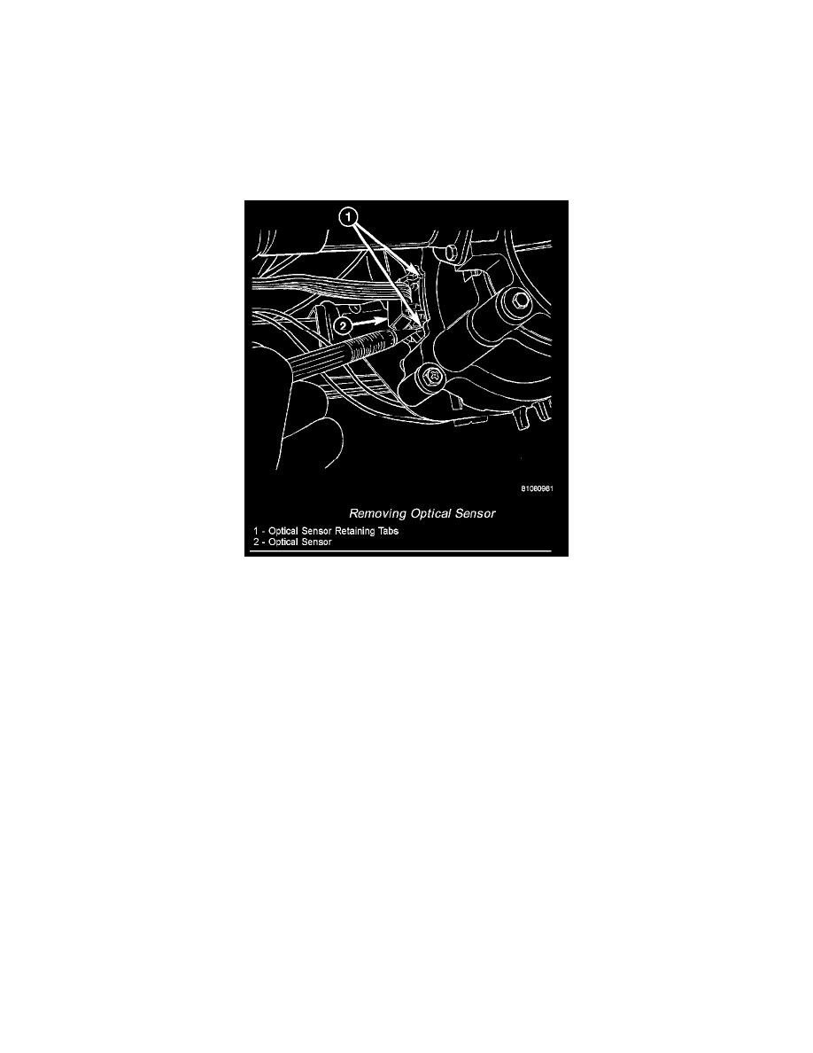
Removing Optical Sensor
5. Using a small flat-bladed tool, depress one of the optical sensor's plastic retaining tabs to unhook the optical sensor from the clutch housing
assembly.
INSTALLATION
NOTE: Be certain the optical sensor wires are reinstalled in the correct wire cavities. Failure to do so could result in damage to components. Refer to
Wiring Diagrams if previous notes were not made.
1. Perform a wiring repair on the optical sensor wires, or install new terminals on the wire ends and reinstall in the drive unit electrical connector. Be
certain to follow the approved procedure in the Wiring section.
2. Install the optical sensor on the clutch housing assembly.
3. Connect the negative battery cable.
4. Using an appropriate scan tool, check and erase any power liftgate module diagnostic trouble codes.
5. Verify power liftgate system and optical sensor operation. Cycle the power liftgate through one complete open and close cycle, this will allow the
power liftgate module to relearn its cycle with the new components.
6. Install the left rear D-pillar trim panel on the vehicle.