
PT Cruiser L4-2.4L (2008)
Antenna, Radio: Testing and Inspection
DIAGNOSIS AND TESTING - ANTENNA BODY AND CABLE
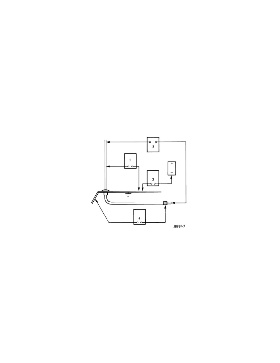
The following four tests are used to diagnose the antenna with an ohmmeter:
-
TEST 1 - Mast to ground test
-
TEST 2 - Tip-of-mast to tip-of-conductor test
-
TEST 3 - Body ground to battery ground test
-
TEST 4 - Body ground to antenna coaxial cable shield test.
WARNING: Disable the airbag system before attempting any steering wheel, steering column, seat belt tensioner, side airbag, or instrument
panel component diagnosis or service. Disconnect and isolate the battery negative (ground) cable, then wait two minutes for the airbag system
capacitor to discharge before performing further diagnosis or service. This is the only sure way to disable the airbag system. Failure to take the
proper precautions could result in accidental airbag deployment and possible personal injury.
The ohmmeter test lead connections for each test are shown in the illustration.
NOTE: This model has a two-piece antenna coaxial cable. Tests 2 and 4 must be conducted in two steps to isolate an antenna cable problem.
First, test the primary antenna cable (integral to the antenna body and cable) from the coaxial cable connector under the right end of the
instrument panel near the right cowl side inner panel to the antenna body. Then, test the secondary antenna cable (instrument panel antenna
cable) from the coaxial cable connector under the right end of the instrument panel near the right cowl side inner panel to the coaxial cable
connector at the radio.
TEST 1
Test 1 determines if the antenna mast is insulated from ground. Proceed as follows:
1. Disconnect and isolate the antenna coaxial cable connector under the right end of the instrument panel near the right cowl side inner panel.
2. Touch one ohmmeter test lead to the tip of the antenna mast (below tip if ball tip is plastic). Touch the other test lead to the antenna cap nut. Check
the ohmmeter reading for continuity.
3. There should be no continuity. If OK, go to Test 2. If not OK, replace the faulty antenna body and cable.
TEST 2
Test 2 checks the antenna conductor components for an open circuit. This test should be performed first on the entire antenna circuit, from the antenna
mast to the center conductor of the coaxial cable connector at the radio. If an open circuit is detected, each of the three antenna conductor components
(antenna mast, antenna body and primary cable unit, instrument panel antenna secondary cable) should be isolated and tested individually to locate the
exact component that is the source of the open circuit. To begin this test, proceed as follows:
1. Disconnect the instrument panel (secondary) antenna cable coaxial connector from the back of the radio.
2. Touch one ohmmeter test lead to the tip of the antenna mast. Touch the other test lead to the center conductor pin of the instrument panel antenna
cable coaxial connector for the radio. Check the ohmmeter reading for continuity.
3. There should be continuity. The ohmmeter should register only a fraction of an ohm resistance. High or infinite resistance indicates a damaged or
open antenna conductor. If OK, go to Test 3. If not OK, isolate and test each of the individual antenna conductor components. Replace only the
faulty antenna conductor component.