
PT Cruiser L4-2.4L (2008)
position sensor, manifold absolute pressure sensor, throttle position sensor, A/C pressure switch, A/C pressure transducer, and vehicle speed sensor.
Powertrain Control Module Connectors
The PCM is an engine and transmission controller module all in one, if the vehicle is equipped with an automatic transmission. The PCM uses four
wiring harness connectors to receive and send engine and transmission data. To ease assembly, the mating wiring harness connector is color-coded. Each
module connector cavity has its own unique color identification stripe located on the outside of each connector cavity.
The PCM module utilizes four wiring harness connectors as described:
-
Connector Cavity A is for Power & Ground (Black)
-
Connector Cavity B is for Engine Side (Orange)
-
Connector Cavity C is for Headlamp & Dash (White)
-
Connector Cavity D is for Transmission (Green) If equipped
NOTE: Connector Cavities A, B, C, And D must be connected prior to battery connection and ignition key on to avoid setting erroneous
controller fault codes. It is also recommended that cavity A connector is made prior to any other connectors.
TRANSMISSION CONTROL
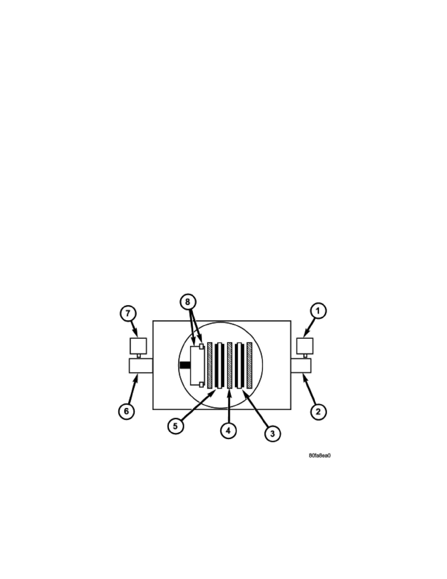
CLUTCH VOLUME INDEX (CVI)
An important function of the PCM is to monitor Transmission Clutch Volume Index (CVI). CVIs represent the volume of fluid needed to compress a
clutch pack.
The PCM monitors gear ratio changes by monitoring the Input and Output Speed Sensors. The Input, or Turbine Speed Sensor sends an electrical signal
to the PCM that represents input shaft rpm. The Output Speed Sensor provides the PCM with output shaft speed information.
By comparing the two inputs, the PCM can determine transaxle gear ratio. This is important to the CVI calculation because the PCM determines CVIs by
monitoring how long it takes for a gear change to occur.
Gear ratios can be determined by using the scan tool and reading the Input/Output Speed Sensor values in the "Monitors" display. Gear ratio can be
obtained by dividing the Input Speed Sensor value by the Output Speed Sensor value.
For example, if the input shaft is rotating at 1000 rpm and the output shaft is rotating at 500 rpm, then the PCM can determine that the gear ratio is 2:1.
In direct drive (3rd gear), the gear ratio changes to 1:1. The gear ratio changes as clutches are applied and released. By monitoring the length of time it
takes for the gear ratio to change following a shift request, the PCM can determine the volume of fluid used to apply or release a friction element.
The volume of transmission fluid needed to apply the friction elements are continuously updated for adaptive controls. As friction material wears, the
volume of fluid need to apply the element increases.
Certain mechanical problems within the clutch assemblies (broken return springs, out of position snap rings, excessive clutch pack clearance, improper