
PT Cruiser L4-2.4L Turbo (2009)
clutch pedal at rest (not depressed). If the starter cranks, proceed to the electrical test to determine whether the switch is defective or the circuit is
shorted. If the vehicle does not crank, proceed to the next step.
2. With the park brake set and the transaxle IN NEUTRAL, fully depress the clutch pedal and turn the ignition key to the start position. The engine
starter should crank. If the starter does not crank, visually inspect the clutch pedal for obstructions (floor mat, etc.) and for proper installation of
the master cylinder push rod/bushing on the pedal pin. Also make sure the clutch pedal lever contacts and fully closes the switch for LHD and
Diesel RHD applications.
Electrical Test
1. Move ignition key to the "OFF/LOCK" position and remove key.
2. Set park brake.
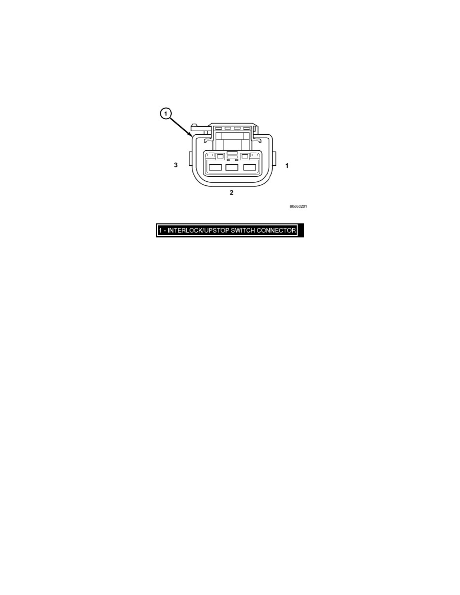
3. Disconnect the clutch interlock/upstop switch connector (1).
4. Using an ohmmeter, check for continuity between terminals 2 AND 3 with the interlock switch not depressed (clutch pedal at rest). There should
be no continuity between the terminals (open circuit).
5. Fully depress the clutch pedal to close the switch. The switch button should compress at least 1.25 mm (0.050 in.) for LHD applications. The
ohmmeter should show continuity (0 ohms).
6. For RHD applications, disconnect the push rod from the pedal pin and actuate the push rod by hand to close the switch. The ohmmeter should
show continuity (0 ohms).
7. If ohmmeter readings do not fall within these ranges, the switch assembly, or the pedal bracket assembly, is defective and should be replaced. If
the switch tests ok, wiring is defective.
UPSTOP SWITCH
NOTE: 2.4L-equipped models (including Turbo) do not use the clutch pedal upstop switch/feature. These vehicles will only utilize the starter
inhibit (interlock) feature. PCM software will not recognize the upstop switch on 2.4L vehicles that have the switch, so upstop switch
testing is not required. Proceed to Speed Control Diagnosis AND Testing. . See: Cruise Control/Testing and Inspection/Component Tests
and General Diagnostics
Mechanical Test (2.2L Turbo Diesel Models)
1. Raise vehicle on hoist.
2. Start engine and operate speed control to maintain speed.
3. Depress clutch pedal at least 33 mm (1.30 in.). Speed control operation should terminate. If speed control does not terminate, the upstop switch is
defective or the related wiring is shorted. Proceed to the upstop switch electrical test.
Electrical Test (2.2L Turbo Diesel Models)
1. Move ignition key to the "OFF/LOCK" position and remove key.
2. Set park brake.
3. Disconnect the clutch interlock/upstop switch connector.
4. Using an ohmmeter, check for continuity between terminals 1 AND 2 with the upstop switch depressed (clutch pedal at rest). The ohmmeter
should show continuity (0 ohms).
5. Depress the clutch pedal at least 33 mm (1.30 in.) and check for continuity between terminals 1 AND 2. There should be no continuity between the
terminals (open circuit).
6. If ohmmeter readings do not fall within these ranges, the switch assembly is defective and should be replaced. If the switch tests ok, wiring is
defective. Refer to Wiring Diagrams and repair defective wiring.
SERVICE DIAGNOSIS - CLUTCH INTERLOCK/UPSTOP SWITCH