
PT Cruiser L4-2.4L Turbo VIN 8 (2005)
ABS TRACTION CONTROL HYDRAULIC CIRCUIT, SOLENOID VALVE, AND SHUTTLE VALVE FUNCTION (ABS WITH
TRACTION CONTROL)
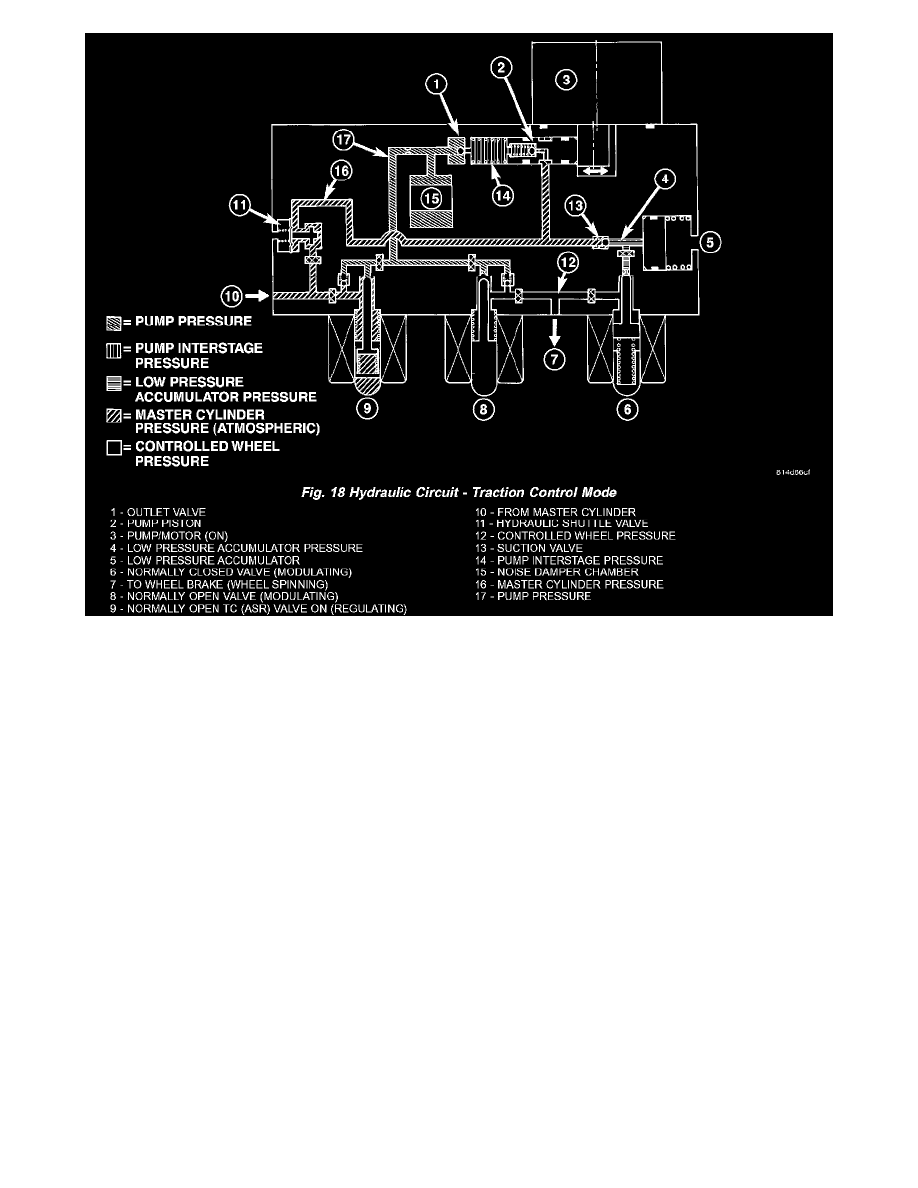
The hydraulic diagram shows the vehicle in the traction control (TC) mode (Fig. 18). The diagram shows a drive wheel is spinning and brake pressure
is required to reduce its speed.
-
The normally open TC (ASR) valve is energized to isolate the brake fluid being pumped from the master cylinder and to isolate the driven wheel.
-
The normally open TC (ASR) valve bypasses the pump output back to the master cylinder at a fixed pressure setting.
-
The normally open and normally closed valves modulate (build/decay) the brake pressure as required to the spinning wheel.
MK25E
DESCRIPTION - MK25E
On Normal Launch production vehicles (which are equipped with the MK25e ABS), the hydraulic control unit (HCU) is mounted to the ABM as part
of the ICU. The HCU controls the flow of brake fluid to the brakes using a series of valves and accumulators. A pump/motor is mounted on the HCU
to supply build pressure to the brakes during an ABS stop.
VALVES AND SOLENOIDS
The valve block contains four inlet valves and four outlet solenoid valves. The inlet valves are springloaded in the open position and the outlet valves
are spring-loaded in the closed position during normal braking. The fluid is allowed to flow from the master cylinder to the wheel brakes.
During an ABS stop, these valves cycle to maintain the proper slip ratio for each wheel. The inlet valve closes preventing further pressure increase and
the outlet valve opens to provide a path from the wheel brake to the HCU accumulators and pump/motor. This releases (decays) pressure from the
wheel brake, thus releasing the wheel from excessive slippage. Once the wheel is no longer slipping, the outlet valve is closed and the inlet valve is
opened to reapply (build) pressure.
If the ABS includes the traction control feature, there are four other valves in the HCU. Two traction control (TC) valves, mounted in the HCU valve
block, are normally in the open position and close only when the traction control is applied. There are also two shuttle valves which control pressure
return to the master cylinder under ABS and traction control conditions.
These TC valves are used to isolate the rear (nondriving) wheels of the vehicle from the hydraulic pressure that the HCU pump/motor is sending to the
front (driving) wheels when traction control is being applied. The rear brakes need to be isolated from the master cylinder when traction control is
being applied so the rear wheels do not drag.