
PT Cruiser L4-2.4L Turbo VIN 8 (2005)
3. Remove the hydraulic brake tube from the proportioning valve controlling the rear wheel of the vehicle that has premature wheel skid.
4. Remove the proportioning valve from its outlet port on the master cylinder.
CAUTION: Be sure the pressure test fittings being installed into master cylinder and proportioning valve, have the correct thread sizes needed.
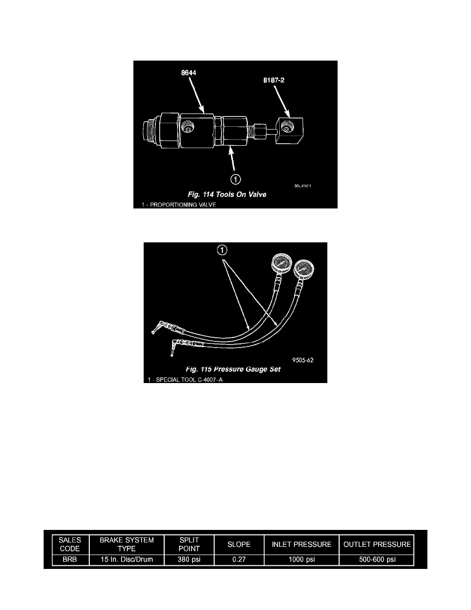
5. Install the Brake Pressure Adapters, Special Tool 8644 and 8187-2 onto the proportioning valve (Fig. 114).
6. Install the proportioning valve (with tools) back into the outlet port on the master cylinder.
7. Attach a Pressure Gauge, Special Tool C-4007-A, to each pressure adapter (Fig. 115).
8. Remove the brake pedal holding tool. Bleed any air out of the pressure gauge hoses at the pressure gauge.
9. With the aid of a helper, apply pressure to the brake pedal until the reading on proportioning valve inlet gauge is at the target inlet pressure shown
in the Brake Proportioning Valve Applications And Pressure Specifications table following this procedure. If the inlet gauge pressure overshoots
its target pressure when the pedal is depressed, release the brake pedal, relieving the pressure in the system, before reapplying the pedal to reach
the target pressure at the inlet gauge. This is necessary to get an accurate reading of the outlet pressure.
10. Once inlet pressure has been achieved, check the pressure reading on the proportioning valve outlet gauge. If the proportioning valve outlet
pressure does not agree with value shown in the table, replace the proportioning valve. If proportioning valve is within pressure specifications, the
valve is good and does not require replacement.
11. Reinstall the brake holding tool on the brake pedal and remove the test equipment from the vehicle.
12. Remove the tools from the proportioning valve.
13. Install the proportioning valve in the master cylinder and hand tighten until the proportioning valve is fully installed and its O-ring seal is seated
into the master cylinder. Tighten the proportioning valve to a torque of 40 Nm (30 ft. lbs.).
14. Install the brake tube on the proportioning valve. Tighten the tube nut to a torque of 17 Nm (145 inch lbs.).
15. Bleed the affected brake line.
BRAKE PROPORTIONING VALVE APPLICATIONS AND PRESSURE SPECIFICATIONS