
PT Cruiser L4-2.4L Turbo VIN 8 (2005)
ABS BRAKING HYDRAULIC CIRCUIT, SOLENOID VALVE, AND SHUTTLE VALVE FUNCTION (ABS WITH TRACTION
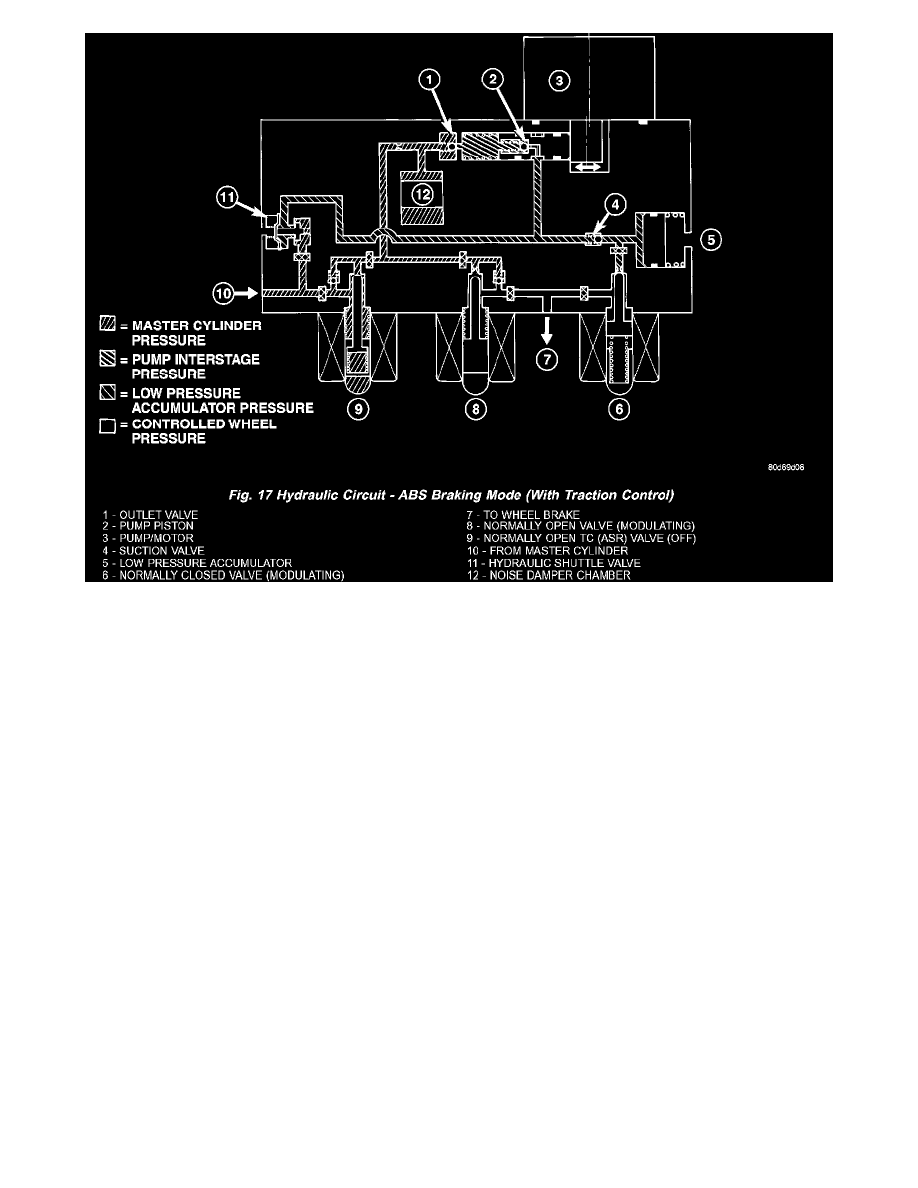
CONTROL)
The hydraulic diagram shows the vehicle in the ABS braking mode (Fig. 17). The diagram shows one wheel is slipping because the driver is
attempting to stop the vehicle at a faster rate than is allowed by the surface on which the tires are riding.
-
The hydraulic shuttle valve closes upon brake application so that the pump/motor cannot siphon brake fluid from the master cylinder.
-
The normally open and normally closed valves modulate (build/decay) the brake hydraulic pressure as required.
-
The pump/motor is switched on so that the brake fluid from the low pressure accumulators is returned to the master cylinder circuits.
-
The brake fluid is routed to either the master cylinder or the wheel brake depending on the position of the normally open valve.