
PT Cruiser L4-2.4L Turbo VIN 8 (2005)
Oxygen Sensor: Description and Operation
OXYGEN SENSORS
Fig. 41 NGK O2 Sensors
The upstream oxygen sensor threads into the outlet flange of the exhaust manifold.
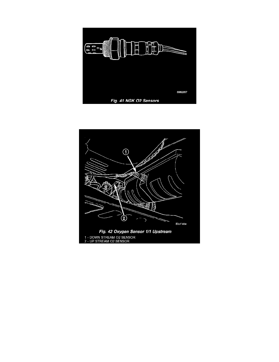
Fig. 42 Oxygen Sensor 1/1 Upstream
The downstream heated oxygen sensor threads into the system depending on emission package. Federal package the O2S is mounted after the catalytic
convertor.
For SBEC vehicles a single sensor ground is used for all 4 O2 sensors (6 Cyl.). A separate upstream and downstream grounds are used on the NGC
vehicles (4 Cyl.).
As vehicles accumulate mileage, the catalytic convertor deteriorates. The deterioration results in a less efficient catalyst. To monitor catalytic
convertor deterioration, the fuel injection system uses two heated oxygen sensors. One sensor upstream of the catalytic convertor, one downstream of
the convertor. The PCM compares the reading from the sensors to calculate the catalytic convertor oxygen storage capacity and converter efficiency.
Also, the PCM uses the upstream heated oxygen sensor input when adjusting injector pulse width.
When the catalytic converter efficiency drops below emission standards, the PCM stores a diagnostic trouble code and illuminates the malfunction
indicator lamp (MIL).
The O2 sensors produce voltages from 0 to 1 volt (this voltage is offset by a constant 2.5 volts on NGC vehicles), depending upon the oxygen content
of the exhaust gas. When a large amount of oxygen is present (caused by a lean air/fuel mixture, can be caused by misfire and exhaust leaks), the
sensors produces a low voltage. When there is a lesser amount of oxygen present (caused by a rich air/fuel mixture, can be caused by internal engine