
PT Cruiser L4-2.4L Turbo VIN 8 (2005)
16. Loosen all six bolts attaching the front suspension crossmember and lower control arms to the body of the vehicle. Do not completely remove the
two bolts going through the lower control arm rear isolator bushings. They are designed to disengage from the body threads yet stay within the
lower control arm rear isolator bushing. Back the two bolts out just enough to disengage the tapping plates in the body of the vehicle. Completely
remove the other four bolts.
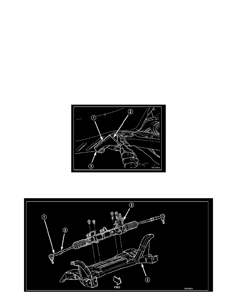
17. Lower the front suspension crossmember (3).
18. Remove each lower control arm from the crossmember by removing the pivot bolts.
INSTALLATION
CAUTION: If the front suspension crossmember is being replaced due to collision damage, inspect the steering column lower coupling for
damage.
1. Install the lower control arms on the front suspension crossmember. Install the pivot bolts, but do not completely tighten them at this time.
2. Using the transmission jack, raise the front suspension crossmember and lower control arms until the crossmember contacts its mounting spot
against the body and frame rails of the vehicle. As the crossmember is raised, carefully guide the power steering gear into mounting position.
3. Start the two crossmember mounting bolts through the lower control arm rear isolator bushings into the tapping plates mounted in the body. Next,
install the two front and the two rear mounting bolts attaching front suspension crossmember to frame rails of vehicle. Lightly tighten all six
mounting bolts to approximately 2 N.m (20 in. lbs.) to hold the front suspension crossmember in position at this time.
NOTE: When reinstalling the front suspension crossmember back in the vehicle, it is very important that the crossmember be attached to the body
in exactly the same spot as when it was removed. Otherwise, the vehicle's wheel alignment settings (caster and camber) will be lost.
4. Using a soft face hammer, tap the front suspension crossmember back-and-forth or side-to-side until it is aligned with the previously scribed
positioning marks (1) on the body of the vehicle. Once the front suspension crossmember is correctly positioned, tighten the two crossmember
mounting bolts through the lower control arm rear isolator bushings to a torque of 250 N.m (185 ft. lbs.), then tighten the four remaining
crossmember mounting bolts to a torque of 153 N.m (120 ft. lbs.).