
Sebring LX Coupe V6-3.0L VIN H (2002)
1. Connect scan tool MB991502 to the data link connector.
2. Check that the tone alarm of scan tool MB991502 sounds when the input signal enters.
Q: Does the tone alarm of scan tool MB991502 sound when the input signal enters?
YES : Go to Step 4.
NO : Scan tool MB991502 does not sound when the ignition switch is turned from "ACC" to "ON": Refer to Inspection Procedure O-2 "The
ignition switch (IG1) signal is not sent to the ETACS-ECU.
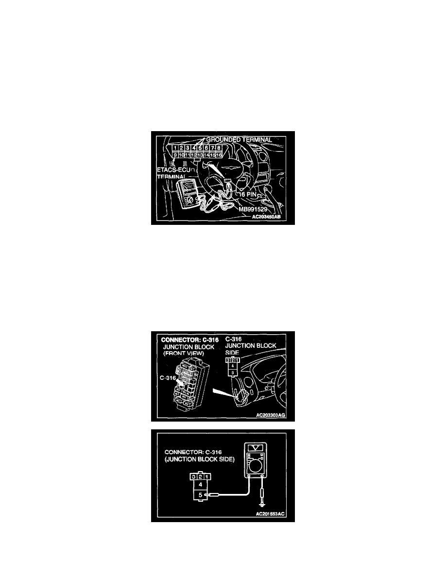
STEP 3. Check the input signal (by using a voltmeter).
Check the input signals from the ignition switch (IG1).
1. Use special tool MB991529 to connect a voltmeter between ground terminal 4 or 5 and ETACS-ECU terminal 9 of the data link connector.
2. Check that the voltmeter indicator deflects once when the input signal enters.
Q: Does the voltmeter indicator deflect?
YES : Go to Step 4.
NO : The voltmeter needle does not fluctuate when the ignition switch is turned from "ACC" to "ON": Refer to Inspection Procedure O-2
"The ignition switch (IG1) signal is not sent to the ETACS-ECU."
STEP 4. Check the battery power supply circuit to the power window relay. Test at power window relay connector C-316.
1. Disconnect power window relay connector C-316 and measure the voltage available at the junction block side of the connector.
2. Measure the voltage between terminal 5 and ground.
-
The voltage should measure approximately 12 volts (battery positive voltage).