
Sebring Sedan L4-2.4L VIN J (2004)
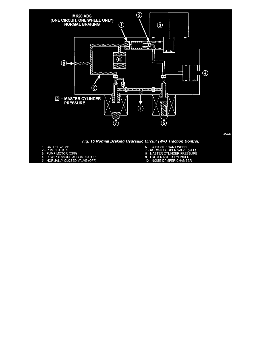
The hydraulic diagram (Fig. 15) shows the vehicle in the normal braking mode of the base brake hydraulic system. The diagram shows no wheel spin
or slip occurring relative to the speed of the vehicle. The driver is applying the brake pedal which builds pressure in the brake hydraulic system to
engage the brakes and stop the vehicle.
ABS HYDRAULIC CIRCUIT AND SOLENOID VALVE FUNCTION (ABS WITHOUT TRACTION CONTROL)