
Sebring Sedan L4-2.4L VIN J (2004)
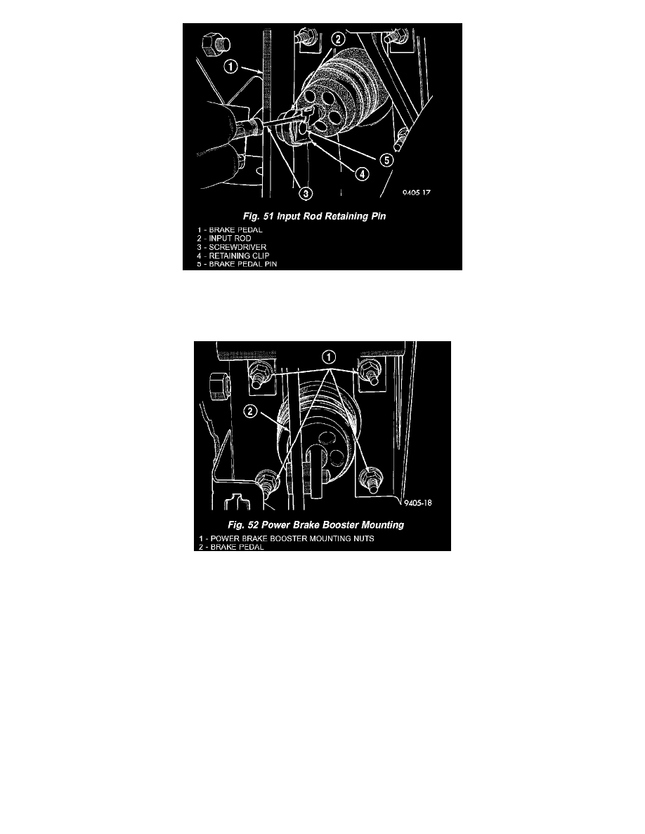
8. Locate the power brake vacuum booster input rod to brake pedal attachment under instrument panel. Position a small screwdriver between the
center tang on the power brake booster input rod to brake pedal pin retaining clip (Fig. 51).
Rotate screwdriver enough to allow retaining clip center tang to pass over end of brake pedal pin. Then pull retaining clip off brake pedal pin.
Discard retaining clip. Replace only with a new retaining clip when assembled.
9. Remove the 4 nuts attaching power brake vacuum booster to dash panel. Nuts are accessible from under dash panel in area of the steering column
and pedal bracket assembly (Fig. 52).
10. Slide power brake vacuum booster straight forward until mounting studs clear dash panel, and remove from vehicle.
CAUTION: Do not attempt to disassemble the power brake vacuum booster it is to be serviced ONLY as a complete assembly.
INSTALLATION
1. Position power brake booster onto dash panel.
2. Install and torque the 4 power brake vacuum booster mounting nuts (Fig. 52) to 29 Nm (250 inch lbs.) torque.
3. Using lubricate, or an equivalent, coat the surfaces of the brake pedal pin that contact the power brake vacuum booster input rod.
4. Connect power brake vacuum booster input rod to brake pedal pin and install a NEW retaining clip. Use only a new retainer clip DO NOT USE
the old clip.
5. Install the purge solenoid to the left frame rail and connect its wiring harness (Fig. 50).
6. Install the vacuum hoses on the booster check valve.
7. Install the master cylinder and connect the fluid level switch.
8. If equipped, install speed control servo on the mounting studs. Install the 2 speed control servo bracket mounting nuts and tighten to a torque of 6
Nm (55 inch lbs.). Install electrical connector and vacuum hose on speed control servo.
9. Install the throttle cable, and if equipped, the speed control cable on the cam of the throttle body assembly.
10. Install the remote ground cable on the ground stud located on the left strut tower. Install and securely tighten the ground cable attaching nut.
11. Check brake lamp operation. If required, adjust brake lamp switch as necessary.