
Town & Country V6-3.3L VIN R (2003)
both connections high or both connections low, the mode door stops and will not move. These same motor connections also provide a feedback
signal to the heater-A/C control module. This feedback signal allows the module to monitor the operation and relative position of the mode door
actuator and the mode door. The heater-A/C control module learns the mode door stop positions during the calibration procedure and will store a
Diagnostic Trouble Code (DTC) for any problems it detects in the mode door actuator circuits. The mode door actuator can be diagnosed using a
DRB III scan tool. Refer to the appropriate diagnostic information.
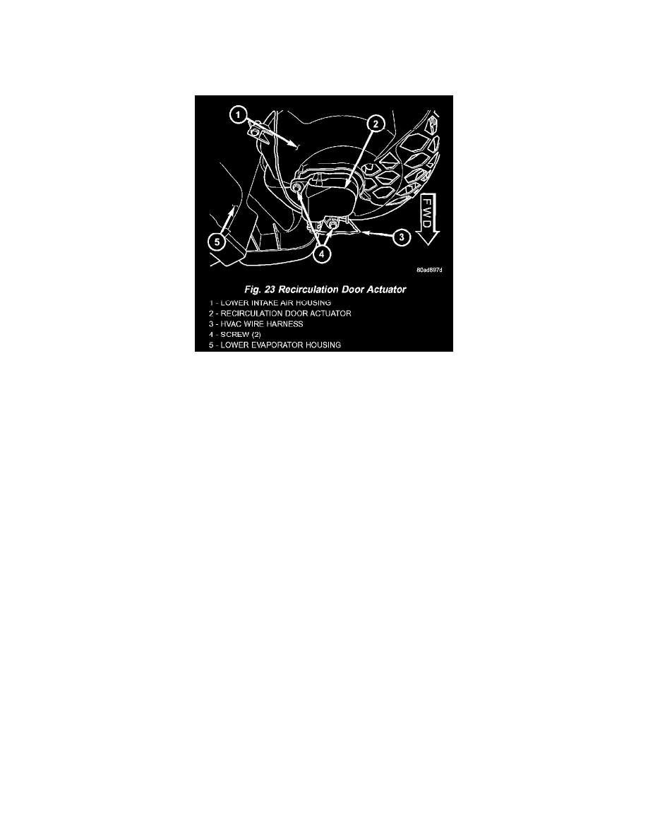
Fig.23 Recirculation Door Actuator
RECIRCULATION DOOR ACTUATOR
The recirculation door actuator is a reversible, 12-volt Direct Current (DC), servo motor. The single recirculation door actuator is located on the
passenger side end of the heater-A/C housing unit, on the bottom of the lower intake air housing. The recirculation door actuator is mechanically
connected to the recirculation air door. The recirculation door actuator is interchangeable with the actuators for the blend air door(s) and the mode
door. Each actuator is contained within an identical black molded plastic housing with an integral wire connector receptacle. Two integral
mounting tabs allow the actuator to be secured with two screws to the lower intake air housing. Each actuator also has an identical output shaft
with splines that connects it to the linkage that drives the recirculation air door. The recirculation door actuator does not require mechanical
indexing to the recirculation air door, as it is electronically calibrated by the heater-A/C control module. The recirculation door actuator cannot be
adjusted or repaired and, if damaged or faulty it must be replaced.
The recirculation door actuator is connected to the heater-A/C control module through the vehicle electrical system by a dedicated two-wire take
out and connector of the HVAC wire harness. The recirculation door actuator can move the recirculation door in two directions. When the
heater-A/C control module pulls the voltage on one side of the motor connection high and the other connection low, the recirculation air door will
move in one direction. When the module reverses the polarity of the voltage to the motor, the recirculation air door moves in the opposite
direction. When the module makes the voltage to both connections high or both connections low, the recirculation air door stops and will not
move. These same motor connections also provide a feedback signal to the heater-A/C control module. This feedback signal allows the module to
monitor the operation and relative position of the recirculation door actuator and the recirculation air door. The heater-A/C control module learns
the recirculation air door stop positions during the calibration procedure and will store a Diagnostic Trouble Code (DTC) for any problems it
detects in the recirculation door actuator circuits. The recirculation door actuator can be diagnosed using a DRB III scan tool. Refer to the
appropriate diagnostic information.