
Town & Country AWD V6-3.8L VIN L (2003)
Drive/Propeller Shaft: Description and Operation
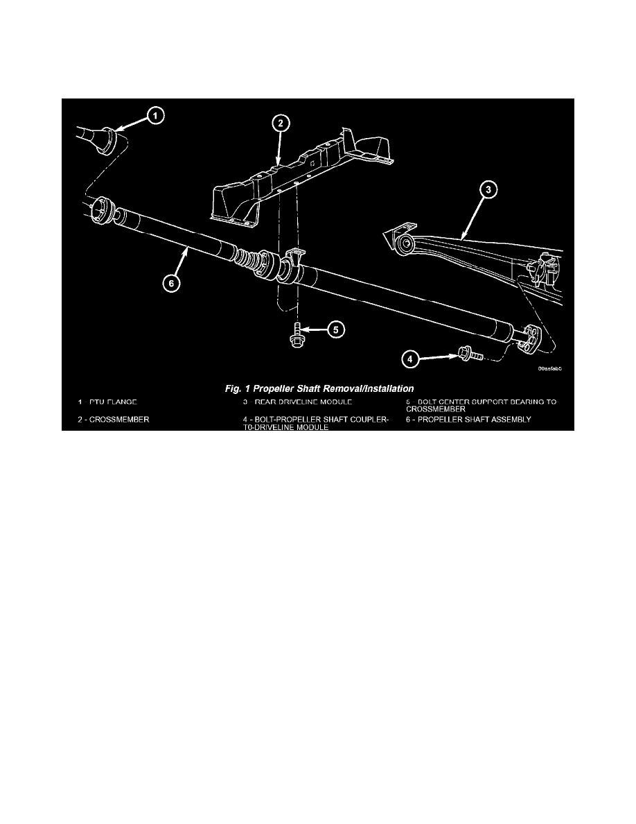
PROPELLER SHAFT / DESCRIPTION
WARNING: Due to propeller shaft imbalance concerns, the propeller shaft can only be serviced as an assembly.
AWD models utilize a "two-piece" propeller shaft (Fig. 1) to transmit power to the rear driveline module assembly. This two-piece design consists of:
-
Front and rear shaft segments. . Plunging center CV joint
-
Center support bearing
-
Rubber coupler at driveline module flange
The front shaft segment utilizes a CV joint at the power transfer unit connection, and a plunging CV joint at the center bearing location.
The rear shaft segment utilizes a center support bearing at the forward position, and a rubber coupler at the driveline module flange.
OPERATION
The propeller shaft (Fig. 1) is used to transmit torque from the transaxle Power Transfer Unit (PTU) to the rear driveline module of AWD equipped
models.
The propeller shaft front half utilizes a CV joint at the PTU flange, and a plunging CV joint at the center bearing location. These joints are flexible,
allowing for torsional movement of the powertrain.
The propeller shaft rear half utilizes a center support bearing, which supports this two-piece assembly. The bearing also stabilizes the rear shaft segment
to minimize axle wind-up. The rubber coupler at the driveline module flange dampens out propeller shaft torsional vibrations, as the driveline module it
connects to is fastened to the vehicle body.