
Town & Country Van 2WD V6-230 3.8L VIN L SMFI (1997)
Load Compensator: Testing and Inspection
WARNING: The use of after-market load leveling or load capacity increasing devices on this vehicle are prohibited. Using air shock absorbers
or helper springs on this vehicle will cause the height sensing proportioning valve to inappropriately reduce the hydraulic pressure to the rear
brakes. This inappropriate reduction in hydraulic pressure potentially could result in increased stopping distance of the vehicle.
CONDITIONS
Overview
When a premature rear wheel skid is obtained on a brake application, it may be an indication that the hydraulic pressure to the rear brakes is above
the specified output from the proportioning valve. This condition indicates a possible malfunction of the height sensing proportioning valve, which
will require testing to verify that it is properly controlling the hydraulic pressure allowed to the rear brakes. Premature rear wheel skid may also be
caused by an incorrectly adjusted proportioning valve actuator assembly, or contaminated front or rear brake linings.
Pre-Checks
Prior to testing a proportioning valve for function, check that all tire pressures are correct. Also, ensure the front and rear brake linings are in
satisfactory condition. It is also necessary to verify that the brakes shoe assemblies on a vehicle being tested, are either Original Equipment
Manufacturers (OEM), or original replacement brake shoe assemblies meeting the OEM lining material specification. The vehicles brake system
is not balanced for after market brake shoe assembly lining material. If both front and rear brakes check OK, proceed to verify that the actuator
assembly for the height sensing proportioning valve is adjusted correctly. Refer to Adjustments. If the proportioning valve is adjusted correctly,
proceed with the test procedure for the height sensing proportioning valve as follows:
PROCEDURE
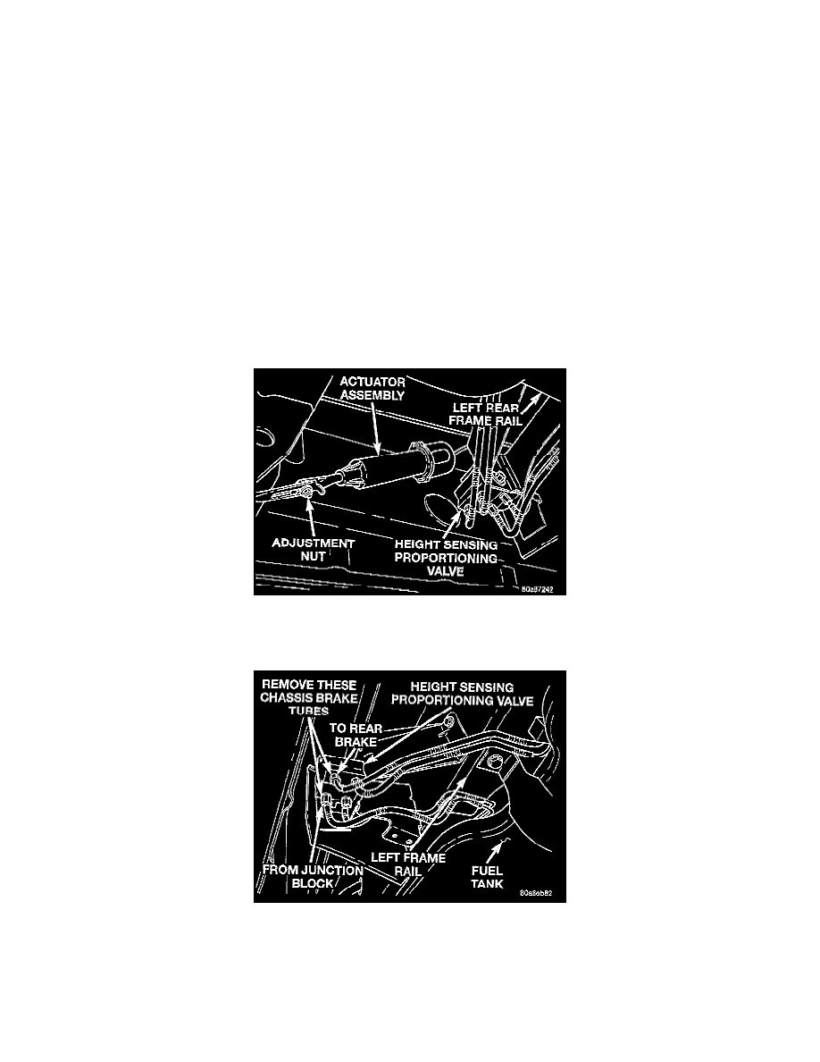
Actuator Assembly And Adjustment Nut
1. Remove the actuator assembly adjustment nut. Remove the actuator assembly from the lever on the height sensing proportioning valve.
Brake Tube Connections To Proportioning Valve
2. Remove the chassis brake tube coming from the junction block from the front of the height sensing proportioning valve. Remove the chassis brake
tube going to the rear brakes from the back of the height sensing proportioning valve.