
Voyager L4-2.4L VIN B (2001)
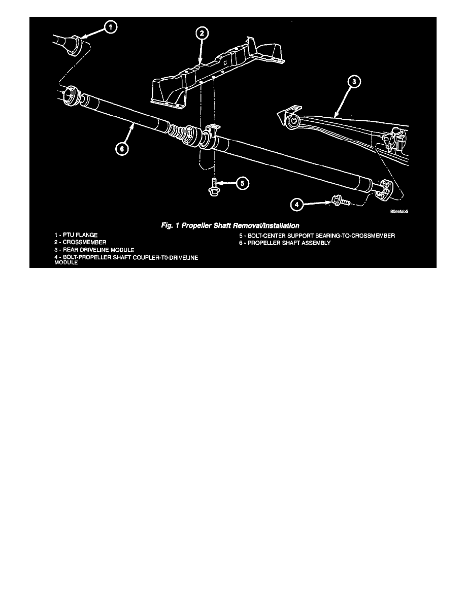
2. Obtain a helper and lift propeller shaft assembly into position (Fig. 1).
3. While helper supports front half of shaft level to underbody, align paint marks at driveline module flange and install three propeller shaft rubber
coupler-to-rear driveline module bolts by hand. Do not torque at this time.
4. While helper supports front half of shaft level to underbody, align chalk marks at PTU flange. Install six propeller shaft-to-PTU flange bolts and
torque to 30 Nm (22 ft. lbs.) Torque bolts alternately to ensure proper flange mating.
5. Place center bearing into position. Install and torque center bearing-to-crossmember bolts to 54 Nm (40 ft. lbs.).
6. Torque propeller shaft rubber coupler-to-rear driveline module assembly to 54 Nm (40 ft. lbs.).