
Lanos S Hatchback L4-1.6L DOHC D-TEC MFI (1999)
Brake Rotor/Disc: Testing and Inspection
ROTOR INSPECTION
Brake rotors are manufactured with close tolerances for thickness variation, flatness, and lateral runout. However, pits and grooves are created in
rotors during usage. The lack of uniformity of the braking surfaces of the rotor can cause inadequate braking and a pulsating pedal during braking. The
surface finish of the rotor is also important because an unsuitable surface finish can cause pulling and rapid wear of the brake shoe lining.
Thickness variation can be checked by measuring the thickness of the rotor at four or more points around the circumference of the rotor. All
measurements must be made at the same distance from the edge of the rotor. A rotor that varies by more than 10 mm (0.004 inch) can cause pedal
pulsations and/or front end vibration during braking. Thickness can be measured with a commercially available brake micrometer. If a rotor does not
meet the specification, it should be refinished to specification or replaced. Refinishing of the rotor should only be done with precision equipment.
Light scoring of the rotor surfaces is acceptable if it does not exceed 0.40 mm (0.016 inch) in depth. Scoring measurements can be made with a
commercially available brake micrometer.
Lateral runout cannot exceed 0.10 mm (0.004 inch). If lateral runout exceeds the specification, make sure there is no dirt between the rotor and the
hub and that the hub-to-rotor contact surfaces are smooth and free from burrs. Use a commercially available dial indicator to check the lateral runout
according to the following procedure:
1. Position the transaxle in NEUTRAL and raise the vehicle.
2. To preserve wheel balance, mark the relative positions of the wheel and hub, and remove the front wheel.
3. Fasten the brake rotor to the wheel hub with two wheel bolts.
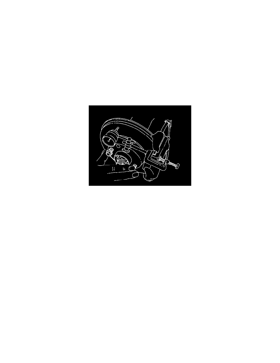
4. Fasten a dial indicator to the brake caliper.
5. Place the gauge tip approximately 10 mm (0.39 inch) from the outer edge of the brake rotor, perpendicular to the disc and under slight preload.
Observe the gauge while rotating the rotor.
6. After the measuring is completed, remove the dial indicator and the wheel bolts.
7. If necessary, refinish the rotor with precision equipment. Measure the runout again after refinishing. If the runout exceeds 0.10 mm (0.004 inch)
after refinishing, the rotor should be replaced.
8. Align the marks that were made before wheel removal and install the front wheel.
9. Lower the vehicle.