
Lanos S Hatchback L4-1.6L DOHC D-TEC MFI (1999)
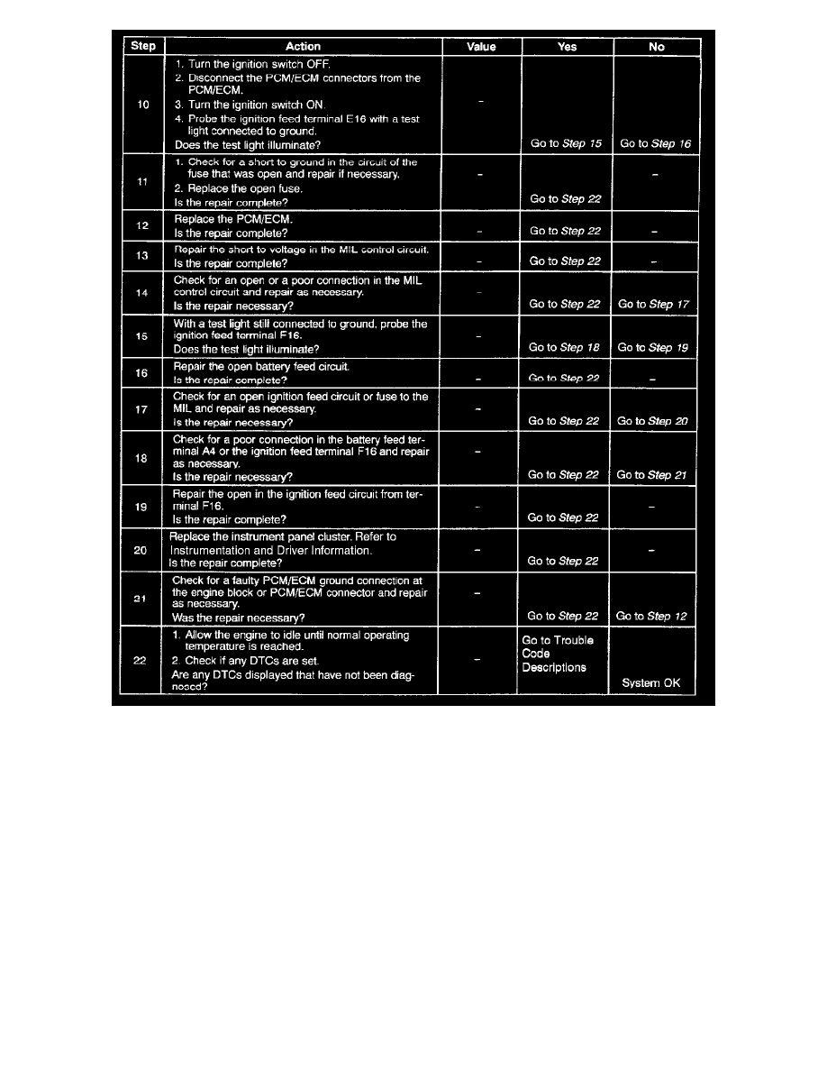
Steps 10 - 22
Test Description
Number(s) below refer to the step number(s) on the diagnostic table.
1. The On-Board Diagnostic (OBD II) System Check prompts the technician to complete some basic checks and to store the freeze frame and failure
records data on the scan tool, if applicable. This creates an electronic copy of the data taken when the malfunction occurred. The information is
stored in the scan tool for later reference.
3. Connections that are suspected of being faulty should be thoroughly checked as described in the diagnostic aids.
4. If the engine fails to start and the MIL is inoperative, then the fault can be isolated to either the PCM/ECM ignition feed, the battery feed, or a
poor ground at the engine block or at the PCM/ECM.
6. Probing the MIL circuit with a test light to ground stimulates the PCM/ECM's control of the MIL. lithe MIL illuminates, then the malfunction can
be isolated to the control of the MIL or a poor connection at the MIL terminal to the PCM/ECM. Connections that are suspected of being faulty
should be thoroughly checked as described in the diagnostic aids.
8. It takes very little resistance for the battery and the ignition feed circuits to cause an intermittent condition and should also be checked for a poor
connection as described in diagnostic aids
11. Before replacing the PCM/ECM, check for backed cut terminals, improper mating broken locks, improperly formed or damaged terminals, and
poor terminal to wiring harness. Replacement PCMs must be reprogrammed. Refer to the latest Techline information for reprogramming
procedures.
20. PCM/ECM grounds will only cause a problem if all of the grounds are not making a good connection. If a PCM/ECM ground problem is