
Lanos S Hatchback L4-1.6L DOHC D-TEC MFI (1999)
Steps 12 - 18
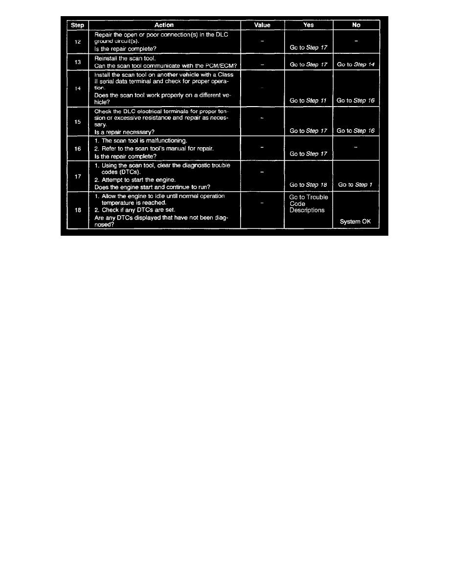
Test Description
Number(s) below refer to the step number(s) on the Diagnostic Table.
1. The Powertrain On-Board (OBD II) System Check prompts the technician to complete some basic checks and store the freeze frame and failure
records data on the scan tool if applicable. This creates an electronic copy of the data taken when the malfunction occurred. The information is
then stored on the scan tool for later reference.
3. Unlike the UART serial data circuit, the only time a Class II serial data circuit has any voltage on it is when a scan tool asks the PCM/ECM for
information and sends the information out.
8. Locate and repair any shorts that may have caused the fuse to open before replacement, if the no voltage condition was due to an open fuse.
11. The replacement PCM/ECM must be programmed. Refer to the latest Tech line procedure for PCM/ECM reprogramming.
16. The scan tool or associated cables could be malfunctioning. Refer to the scan tool's manual for repair information.