
Lanos S Hatchback L4-1.6L DOHC D-TEC MFI (1999)
Powertrain Control Module (PCM)/ Engine Control Module (ECM): Testing and Inspection
PCM/ECM Output Diagnosis
PCM/ECM Output Diagnosis
Circuit Description
The powertrain control module (PCM)/Engine control module (ECM) controls most components with electronic switches which complete a ground
circuit when turned on. These switches are arranged in groups of 4 and 7, and are called either a surface mounted quad driver module, which can
independently control up to 4 output terminals or an Output Driver Module (ODM), which can independently control up to 7 outputs. Not all of the
outputs are always used.
Drivers are fault protected. If a relay or solenoid is shorted, has a very low or zero resistance, or if the control side of the circuit is shorted to voltage, it
would allow too much current flow into the PCM/ECM. The driver senses this, and the output is either turned OFF or its internal resistance increases to
limit the current flow and protect the PCM/ECM and driver. The result is high output terminal voltage when it should be low. If the circuit from B+ to
the component or the component is open, or the control side of the circuit is shorted to ground, terminal voltage will be low. Either of these conditions is
considered to be a driver fault.
Drivers also have a fault line to indicate the presence of a current fault to the PCM/ECM's central processor. A scan tool displays the status of the driver
fault lines as 0=OK and 1=Fault.
Diagnostic Aids
The scan tool has the ability to command certain components and functions ON and OFF. If a component or function does not have this capability,
operate the vehicle during its normal function criteria to check for an open or shorted circuit.
An open or short to ground will appear in the open positions on the scan tool only when it is not commanded by the PCM/ECM or the scan tool. A short
to voltage will appear in the short positions on the scan tool only while the component is being commanded by the PCM/ECM or scan tool.
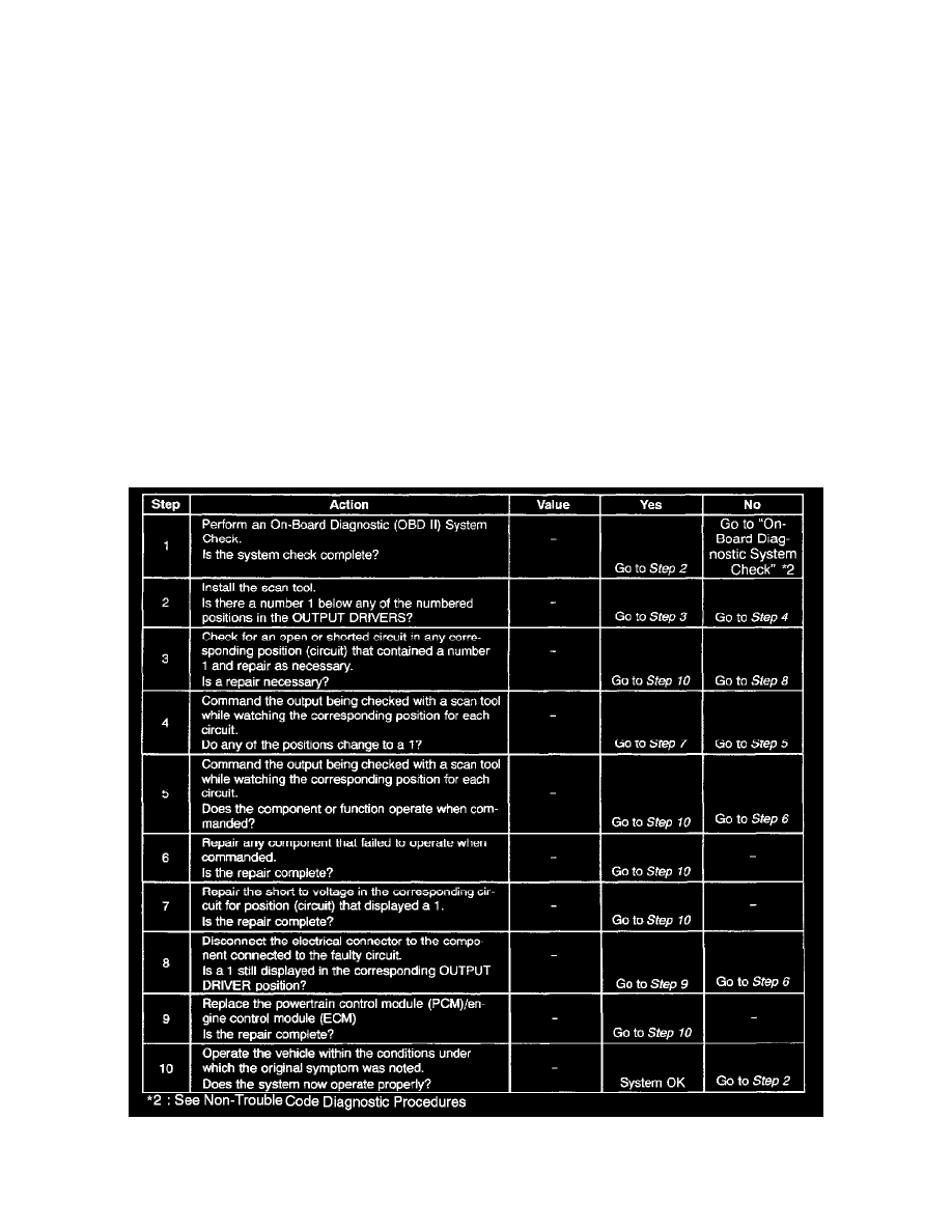
Steps 1 - 10
Test Description