
Lanos S Hatchback L4-1.6L DOHC D-TEC MFI (1999)
Manifold Absolute Pressure (MAP) Sensor: Testing and Inspection
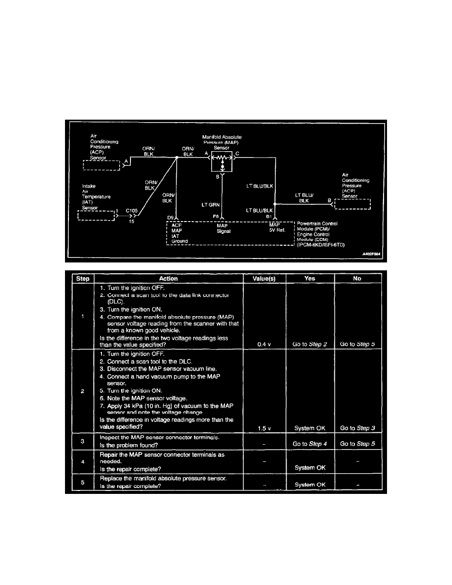
Manifold Absolute Pressure Check
Circuit Description
The manifold absolute pressure (MAP) sensor measures the changes in the intake manifold pressure which result from engine load (intake manifold
vacuum) and rpm changes. The MAP sensor converts these changes into a voltage output. The powertrain control module (PCM)/Engine control module
(ECM) sends a 5-volt reference voltage to the MAP sensor. As the intake manifold pressure changes, the output voltage of the MAP sensor also changes.
A low voltage (high vacuum) output of 1 to 2 volts is present at idle. A high voltage (low vacuum) output of 4.0 to 4.8 volts is present at wide open
throttle. The MAP sensor is also used under certain conditions to measure barometric pressure. This allows the PCM/ECM to make adjustments for
altitude changes. The PCM/ECM uses the MAP sensor for fuel delivery and ignition timing changes.
Steps 1 - 5
Test Description
The number(s) below refer to step(s) on the diagnostic table.
2. Applying 34 kpa (10 inches Hg) of vacuum to the MAP sensor should cause the voltage to change. Subtract the second voltage reading from the
first. That voltage value should be more than 1.5 volts. When applying vacuum to the MAP sensor, the change in the voltage should happen