
Lanos S Hatchback L4-1.6L DOHC D-TEC MFI (1999)
Shift Solenoid: Description and Operation
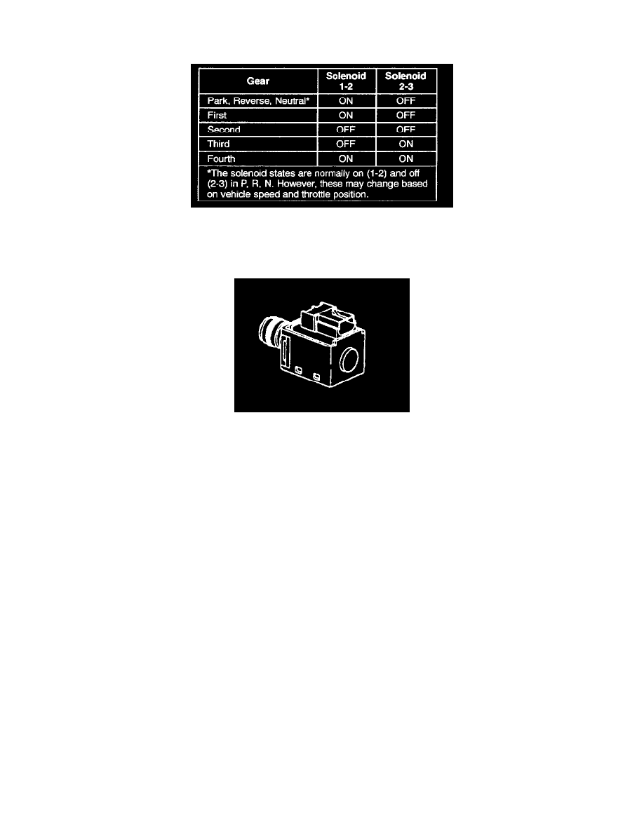
SHIFT SOLENOIDS: 1-2 AND 2-3
The shift solenoids are two identical, normally open electronic exhaust valves that control upshifts and downshifts in all forward gear ranges. These
shift solenoids work together in a combination of ON and OFF sequences to control the positions of the 1-2, 2-3, and 3-4 shift valve trains. The
Powertrain Control Module (PCM) monitors numerous inputs to determine the appropriate solenoid state combination and transmission gear for the
vehicle operating conditions.
The PCM energizes the shift solenoids by providing a ground to the solenoid's electrical circuit. This sends current through the coil winding of the
solenoid, thereby creating a magnetic field. The magnetic field repels the plunger inside the solenoid which seats the solenoid metering ball against the
fluid inlet port. This action prevents the exhaust of fluid through the solenoid and provides an increase in fluid pressure at the end of the shift valves.
This fluid pressure initiates an upshift by moving the shift valves (refer to the oil flow diagrams for a complete description of the hydraulic control of
the shift valves for each gear range).
Shift solenoids resistance should measure between 19 - 24 ohms when measured at 20°C (68°F) and between 24 - 31 ohms when measured at 88°C
(190°F).
The shift solenoids should energize when the voltage is greater than 7.5 volts. The shift solenoids should de-energize when the voltage is less than one
volt.