
Leganza CDX L4-2.2L DOHC D-TEC MFI (1999)
Data Link Connector: Testing and Inspection
Data Link Connector Diagnosis
Circuit Description
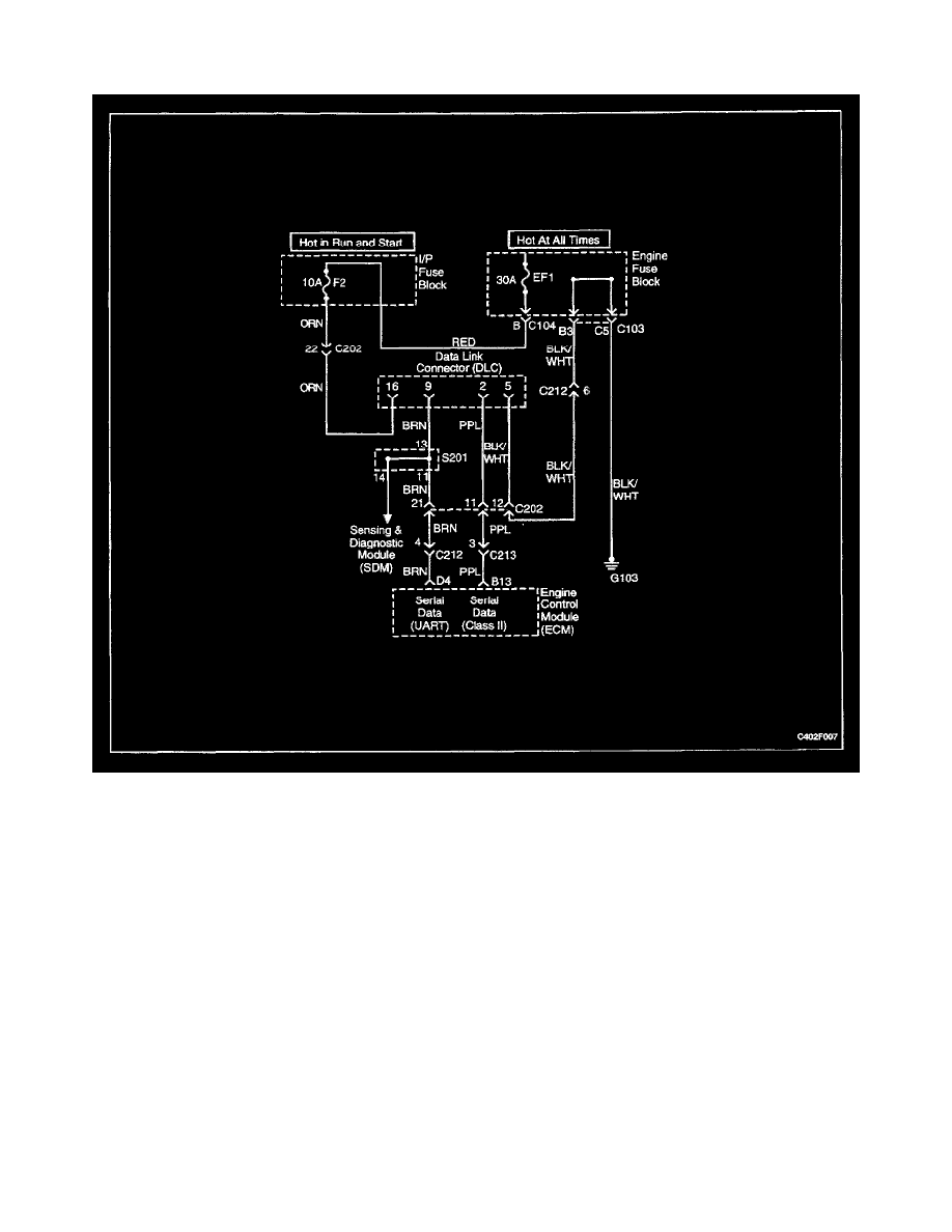
The provision for communicating with the engine control module (ECM) is the Data Link Connector (DLC). It is located under the instrument panel. The
DLC is used to connect the scan tool. Battery power and ground is supplied for the scan tool through the DLC. The Class II serial data circuit 10 the
DLC allows the ECM to communicate with the scan tool. A Universal Asynchronous Receiver Transmitter (UART) serial data line is used to
communicate with the other modules such as the Electronic Brake Control Module (EBCM), the Supplemental Inflatable Restraint (SIR) system and the
Instrument Panel Cluster (IPC).
Diagnostic Aids
Ensure that the correct application (model line, car year, etc.) has been selected on the scan tool. If communication still cannot be established, try the
scan tool on another vehicle to ensure that the scan tool or cables are not the cause of the condition.
An intermittent may be caused by a poor connection, rubbed through wire insulation, or a broken wire inside the insulation.
Any circuitry that is suspected of causing an intermittent complaint should be thoroughly checked for the following conditions:
-
Backed-out terminals.
-
Improper mating of terminals.
-
Broken locks.
-
Improperly formed or damaged terminals.
-
Poor terminal-to-wiring connection.
-
Physical damage to the wiring harness.
-
Corrosion.