
Charade L4-1295cc 1.3L (1989)
Positive Crankcase Ventilation: Description and Operation
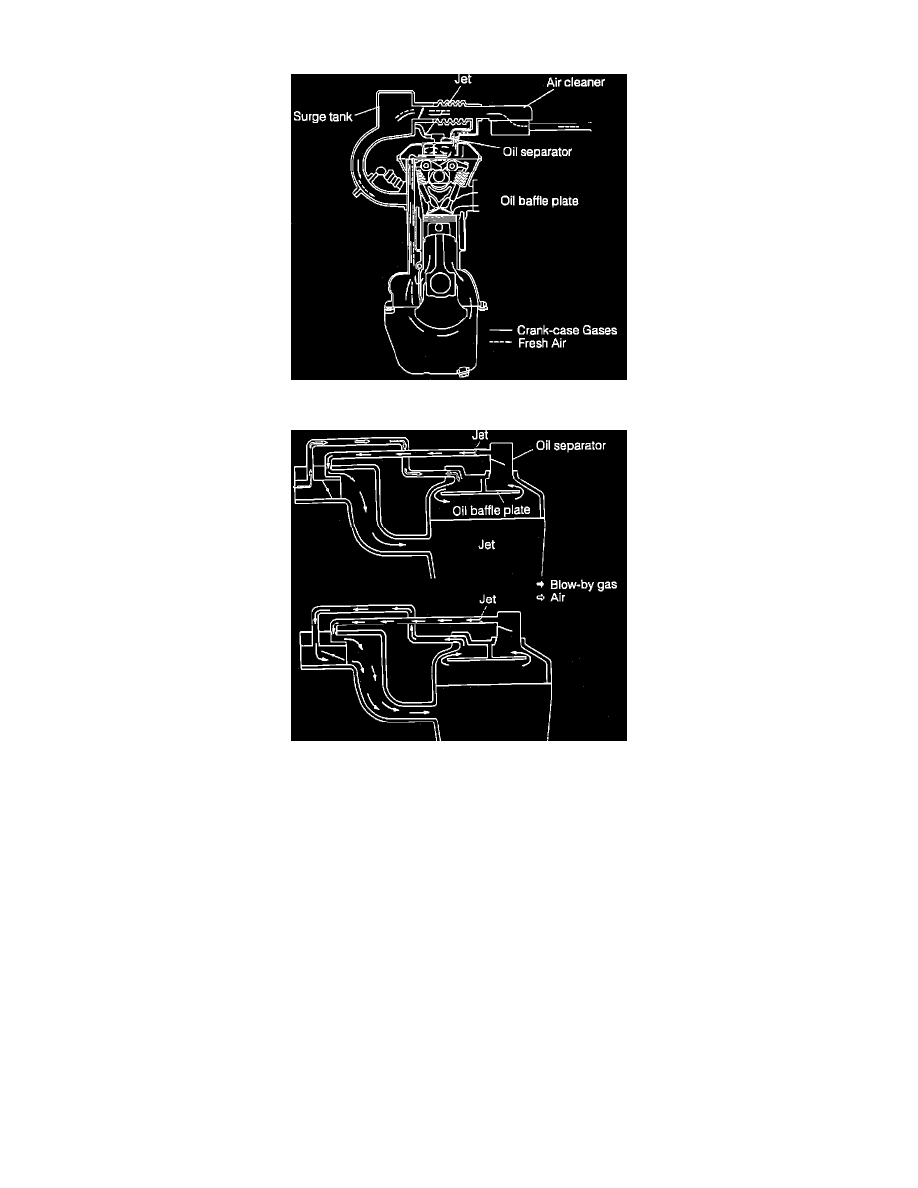
Fig. 1 Positive Crankcase Ventilation System
Fig. 2 Positive Crankcase Ventilation System
This system Figs. 1 and 2, is a closed type PCV system which prevents blow-by gases generated inside the crankcase from being released into the
atmosphere.
The blow-by gases generated flow into the cylinder side, through the gas path, of the cylinder block. When operating degree of the throttle valve is small,
oil in the blow-by gases is separated by the oil separator provided in the cylinder head cover. Then, the blow-by gases are lead into the cylinders from the
throttle body to be burned again.
Fresh air enters the cylinder head cover from the upstream path. At this time, the air flow rate is regulated by a jet provided at the cylinder head cover,
thus stabilizing the engine idle. When the opening degree of the throttle valve is large and/or when a large amount of blow-by gases are generated, the
blow-by gases are lead into the combustion chambers both through the upstream and the downstream paths.