
Caravan AWD V6-201 3.3L (1991)
PARTS REQUIRFD:
1
AS BODY - Door latch with power door lock assembly - Right Side
4675394
1
AS BODY - Door latch with power door lock assembly - Left Side
4675395
1
AB BODY - Door latch with power door lock assembly
55025258
1
2 - Way Connector Package
4419590
REPAIR PROCEDURE:
This procedure involves replacement of the 2-way wiring connector and if required replacing the door latch assembly.
1.
With the ignition key in the OFF position, disconnect the negative battery cable.
2.
Remove the door latch assembly from the door as described in the appropriate service manual.
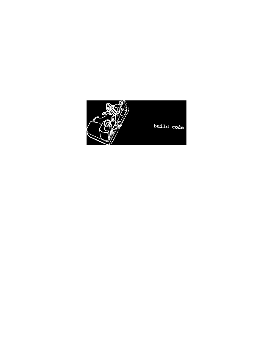
Figure 1
3.
Inspect the door latch assembly build code located on the plastic housing where the door striker engages the latch (Figure 1).
4.
If the build code is 2960 (296th day of 1990) or later, proceed to the 2-WAY CONNECTOR INSTALLATION PROCEDURE, do not replace the
door latch assembly. If the build date is prior to 2960, replace the door latch assembly and the 2-way connector.
5.
Install the appropriate door latch assembly.
2 - WAY CONNECTOR INSTALLATION PROCEDURE
1.
Disconnect the 2-way connector from the door latch assembly.
2.
Cut the leads to the existing 2-way directly behind the insulator and remove about 6 inches of tape from the wiring harness.
3.
Stagger cut the two wires on the vehicle body wiring harness (approximately 1 inch apart).
4.
Cut the matching wires on the new 2-way (from package 4419590) to staggered lengths (allowing extra length for solder connections) so that the
length of the new wiring is the same as the original wiring.
5.
Place a piece of heat shrink tubing onto both wires of the new 2-way connector.
6.
Strip one half inch of insulation from each wire and twist each pair of matching wires together (be sure to match wire colors). Solder each joint
using a ROSIN CORE SOLDER.
7.
Center the heat shrink tubing over the joint and heat using a heat gun. Heat the joint until the tubing is tightly sealed and sealant comes out of both
ends of the tube.
8.
Select the repair connector with the gray ring seal from the 2-way connector package.
9.
Insert the wire terminals into the repair wire connector using the vehicle connector as a guide.
10. Insert the connector locking wedge into the repair connector.
11. Using electrical friction tape, tape the wiring harness to within 1 inch of the repair connector.
12. Connect the repair 2-way connector to the door latch assembly.