
Caravan AWD V6-201 3.3L (1991)
24. Remove intake manifold seal retainers screws Fig. 14. Remove intake manifold gasket.
INSPECTION
Check for:
^
Damage and cracks of each section.
^
Clogged water passages in end crossovers.
INSTALLATION
1. Clean all surfaces of cylinder block and cylinder heads.
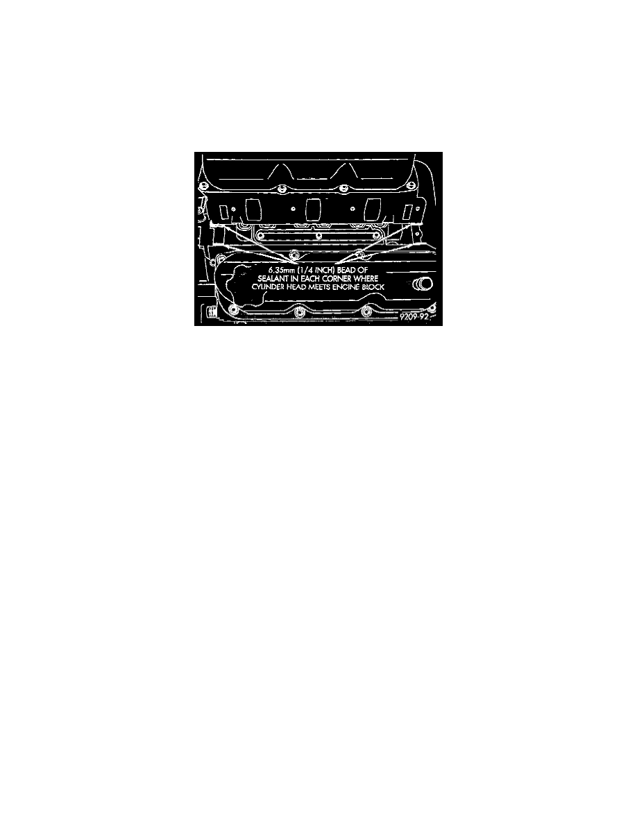
Fig. 15 Intake Manifold Gasket Sealing
2. Place a drop (approximately 1/4 in. diameter) of Mopar Silicone Rubber Adhesive Sealant or equivalent, onto each of the four manifold to
cylinder head gasket corners Fig. 15.
WARNING: Intake manifold gasket is made of very thin metal and may cause personal injury. Handle with care.
3. Carefully install the intake manifold gasket Fig. 14. Torque end seal retainer screws to 12 Nm (105 in.lbs.).
4. Install intake manifold and 8 bolts and torque to 1 Nm (10 in.lbs.). Then retorque bolts to 22 Nm (200 in.lbs.) in sequence shown in Fig. 13. Then
retorque again to 22 Nm (200 in.lbs.). After intake manifold is in place, inspect to make sure seals are in place.
5. Make sure the injector holes are clean and all plugs have been removed.
6. Lube injector O-ring with a drop of clean engine oil to ease installation.
7. Put the tip of each injector into their ports. Push the assembly into place until the injectors are seated in the ports Fig. 12.
8. Install the 4 fuel rail attaching bolts and torque to 22 Nm (200 in.lbs.) Fig. 10.
9. Install fuel tube retaining bracket screw and torque to 4 Nm (35 in.lbs.) Fig. 10.
10. Reconnect cam sensor, coolant temperature sensor and engine temperature sensors Fig. 11.
11. Install fuel injector harness wiring clips on the alternator bracket and intake manifold water tube Fig. 11.
12. Connect fuel pressure regulator vacuum line.
13. Remove covering on lower intake manifold and clean surface.
14. Place intake manifold gasket on lower manifold. Put upper manifold into place and install bolts finger tight.
15. Install the alternator bracket to intake manifold bolt and the cylinder head to intake manifold strut bolts. (Do not torque).
16. Torque intake manifold bolts to 28 Nm (250 in.lbs.) following torque sequence in Fig. 9.
17. Torque alternator bracket to intake manifold bolt to 54 Nm (40 ft.lbs.) Fig. 8.
18. Torque the cylinder head to intake manifold strut bolts to 54 Nm (40 ft.lbs.) Fig. 5.
19. Connect ground strap, MAP and heated oxygen sensor electrical connectors Fig. 6.
20. Connect charge temperature sensor electrical connector Fig. 5.
21. Connect vacuum harness to intake plenum Fig. 5.
22. Using a new gasket, connect the EGR tube flange to the intake manifold and torque to 22 Nm (200 in.lbs.).
23. Clip wiring harness into the hole in the throttle cable bracket.
24. Connect the wiring connectors to the throttle position sensor (TPS) and Automatic Idle Speed (AIS) motor Fig. 4.
25. Connect vacuum harness to throttle body Fig. 4.
26. Install the direct ignition system (DIS) coils. Torque fasteners to 12 Nm (105 in.lbs.) Fig. 8.
27. Lubricate the ends of the chassis fuel tubes with 30 WT. oil. Connect fuel supply and return hoses to chassis fuel tube assembly. Pull back on the
quick connect fitting to ensure complete insertion Fig. 7.
28. Install throttle cable Fig. 3.
29. Connect fuel injector wiring harness.
30. Install air cleaner and hose assembly Fig. 2.
31. Connect negative battery cable. Fill Cooling System. See Cooling System/Service and Repair.
See: Cooling System/Service and Repair